Many of the systems I work with at Formlabs are built on a foundation of laser and galvo control. In an attempt to deepen my understanding of how galvos operate I designed and built a system which would control the projection of light from a laser - a simple laser show demonstration.
Final product.
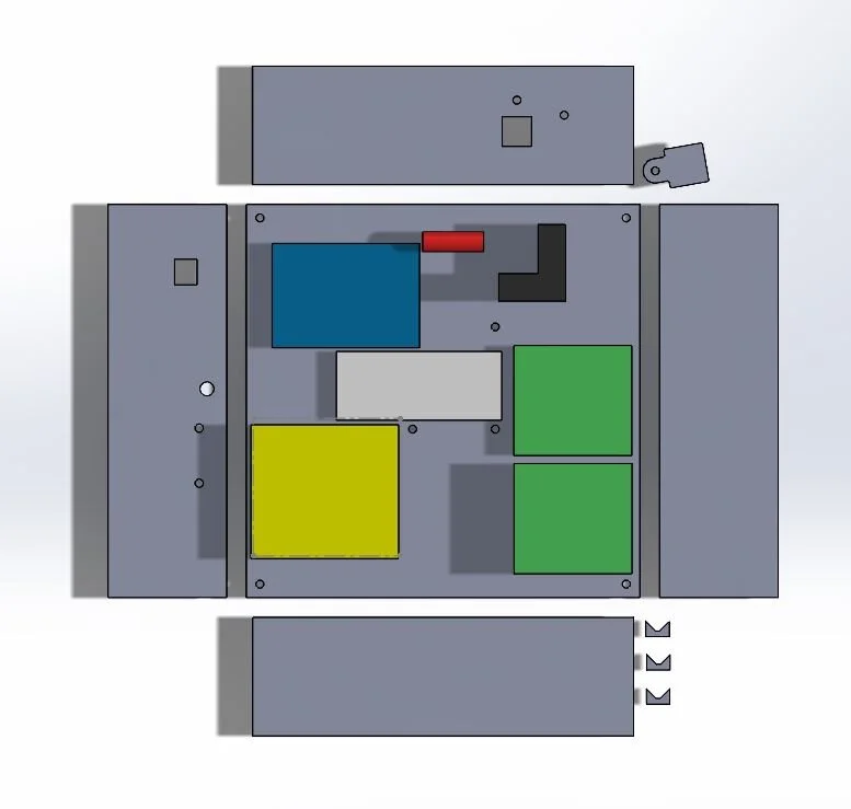
In order for the show to work properly, the laser needed to be well aligned with the galvos - and it was beneficial to have the rest of the components mounted as well. This screenshot shows my design for a protective casing for the whole project, including corresponding screw holes in the base for each component.
Testing the fit of the walls. I wanted the Arduino and power supply to be easily accessible without disassembling the project.
Base assembled with Arduino, galvo block and X and Y galvo drivers.
Laser projector in action. In order to project images, I created DXFs, converted them to G-code, and then converted those paths to hexadecimal, which the Arduino reads and uses to direct the galvos.
Close up of wall with USB mount and power cable ports.
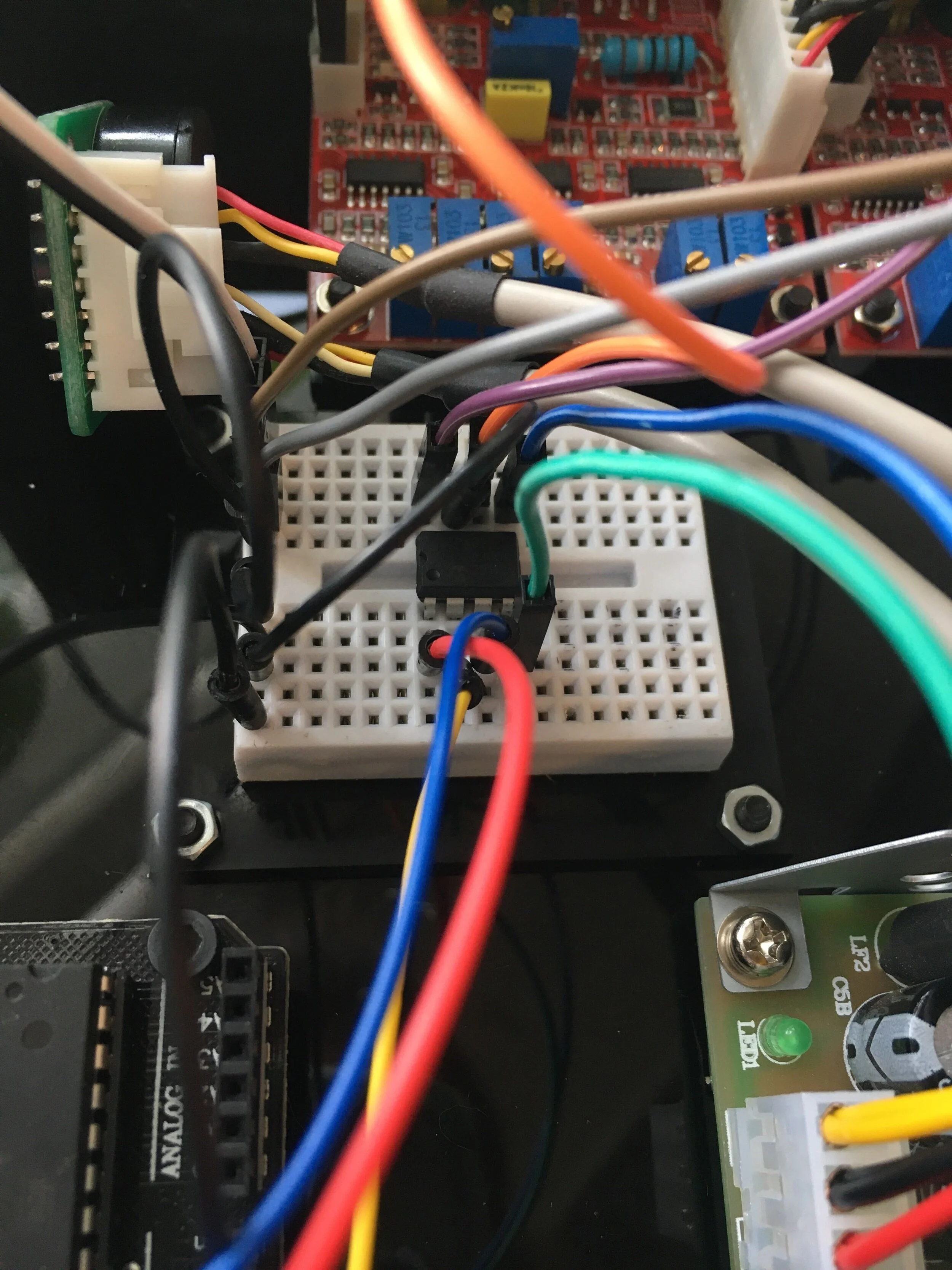
Close up shot of the breadboard - featuring the MCP4822 digital to analog converter microchip which output signals to the galvo drivers from the Arduino.
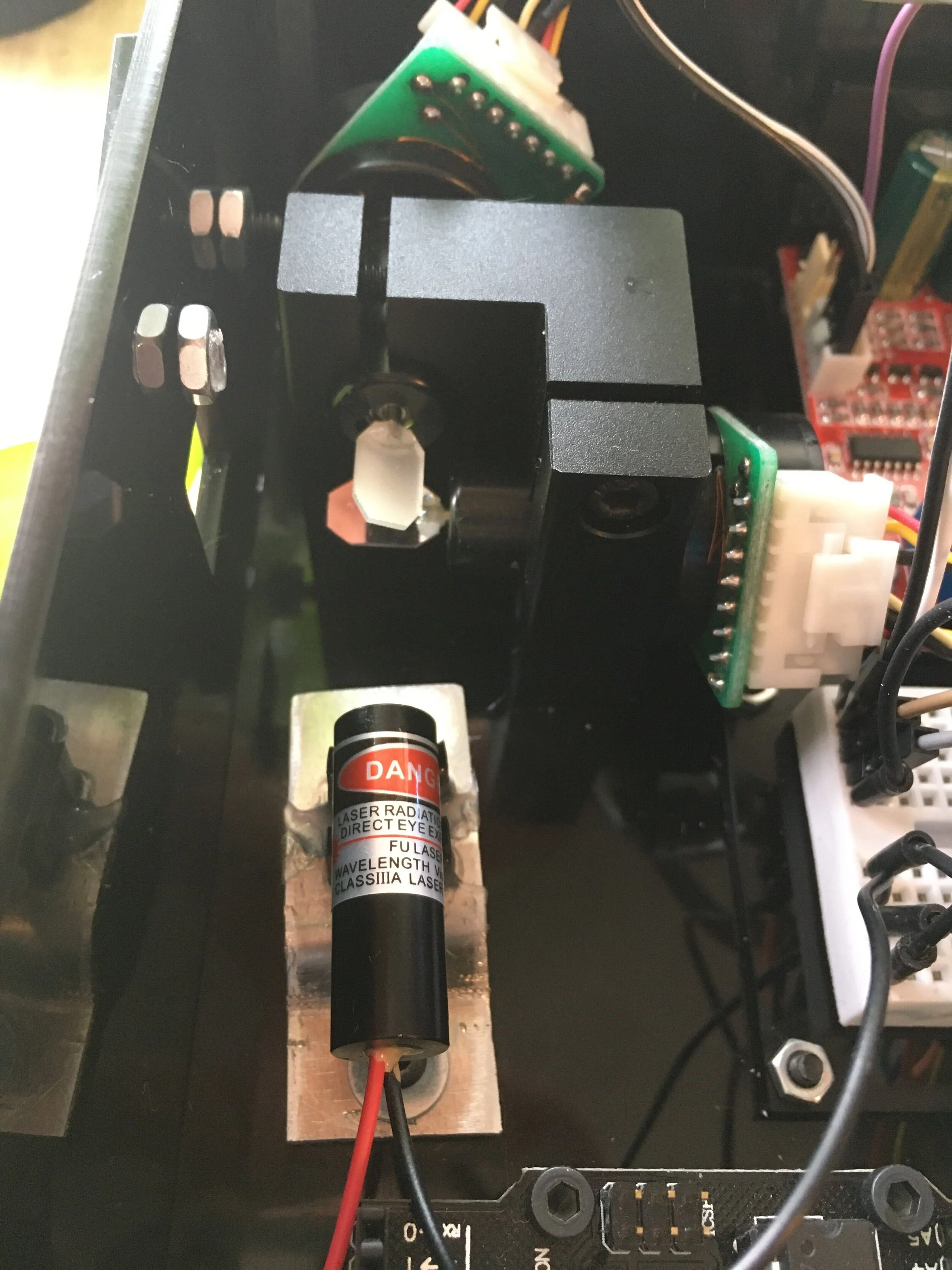
Close up of laser adjustment. In order to for the laser projector to work without skewing, there needs to be good alignment between the laser and each of the galvo mirrors. In order to achieve this, I created a laser mount with horizontal and vertical adjustment.
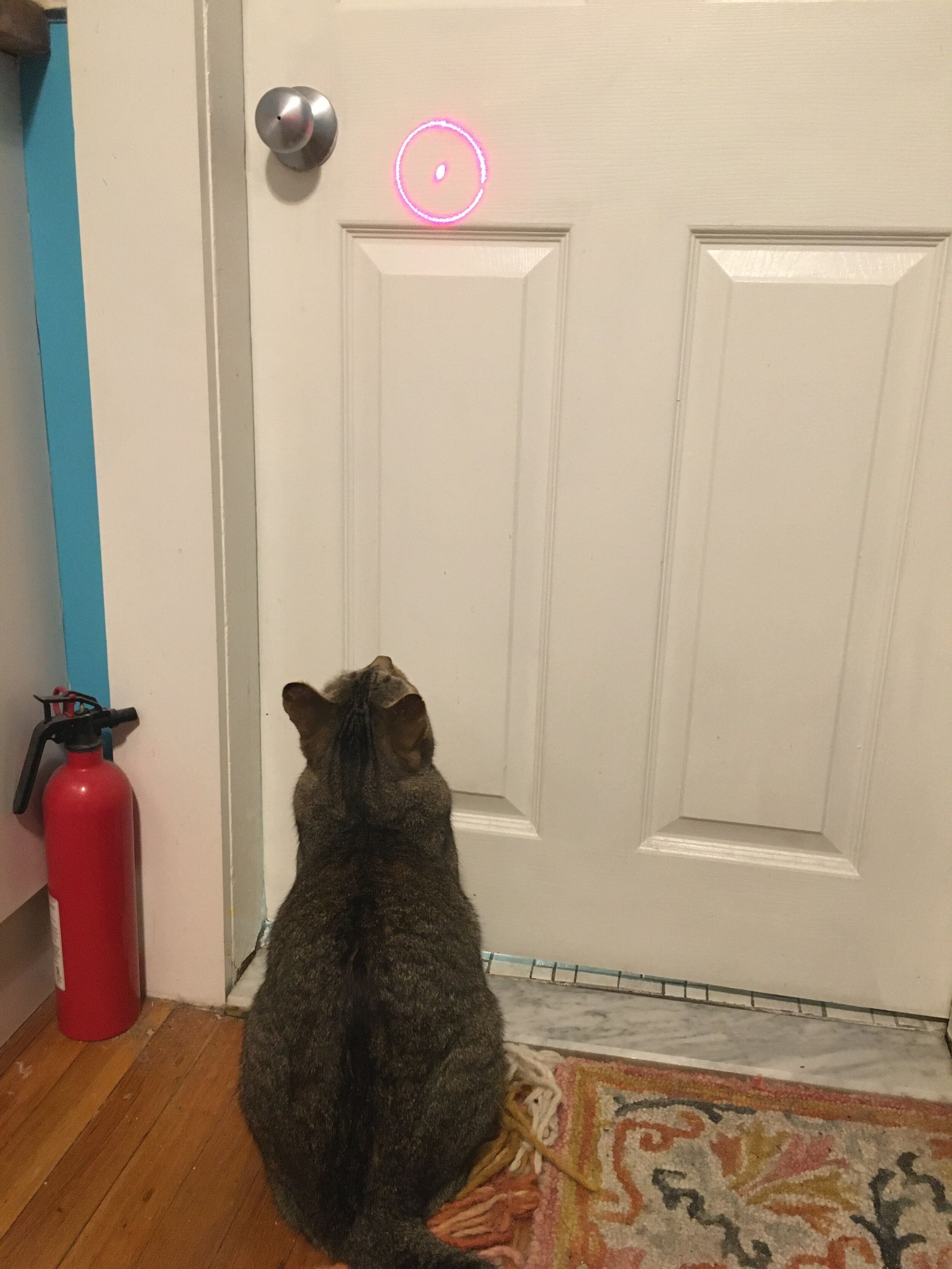
Bodee enjoying the laser show.
Close up of laser window to avoid contamination (or firing the laser at an unsuspecting bystander).
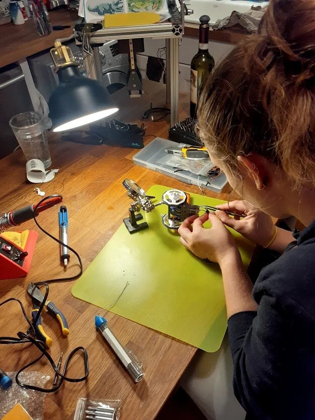
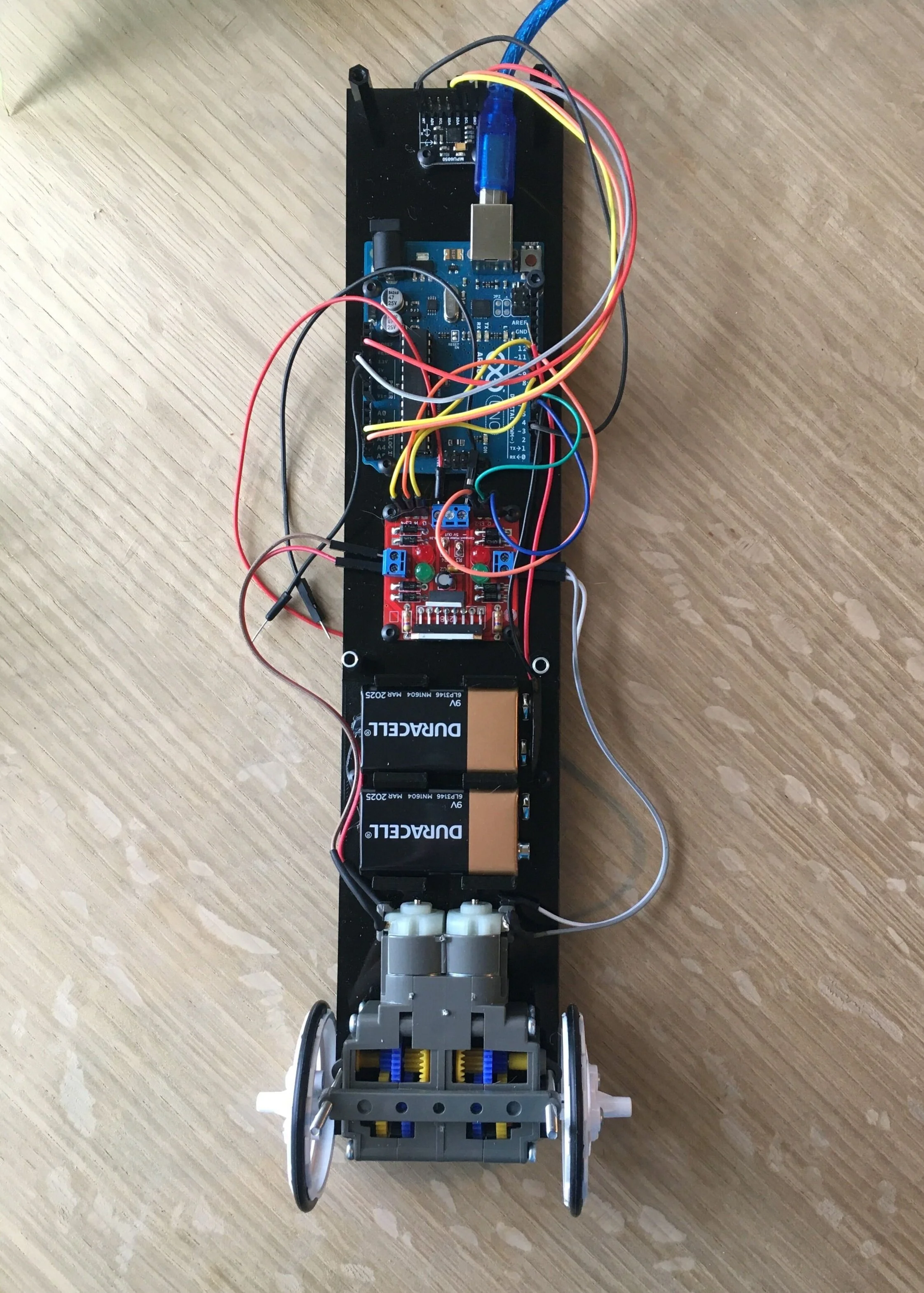
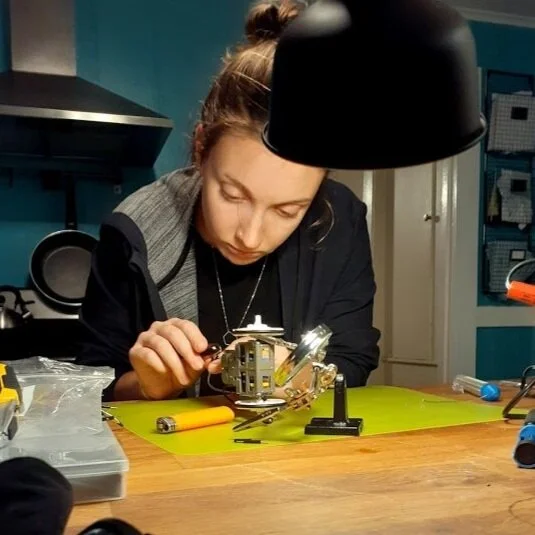
One of my current projects is an inverted pendulum robot. The goal is to build a robot with an IMU which can detect its position and self correct to stay standing upright. This build involved soldering my own motor driver PCB, assembling gear boxes appropriate to the application, reading and interpreting IMU output and writing PID software which allows the robot to stay standing.
Soldering the wires onto the tabs on each motor.
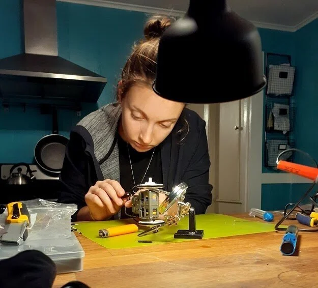
Motor soldering continued. In this image you can see the gear box which I had just assembled.
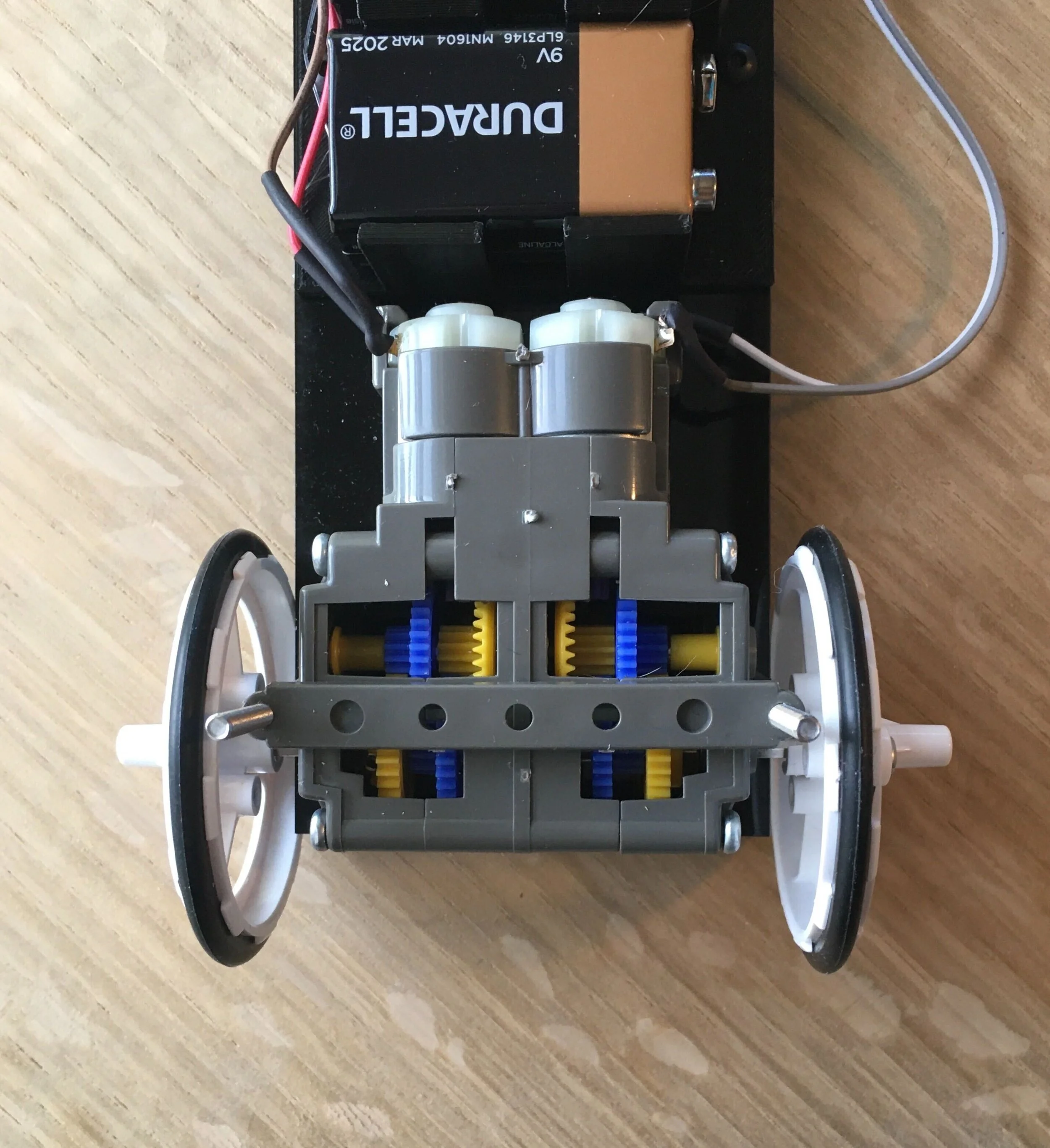
Close up of Tamiya gesa
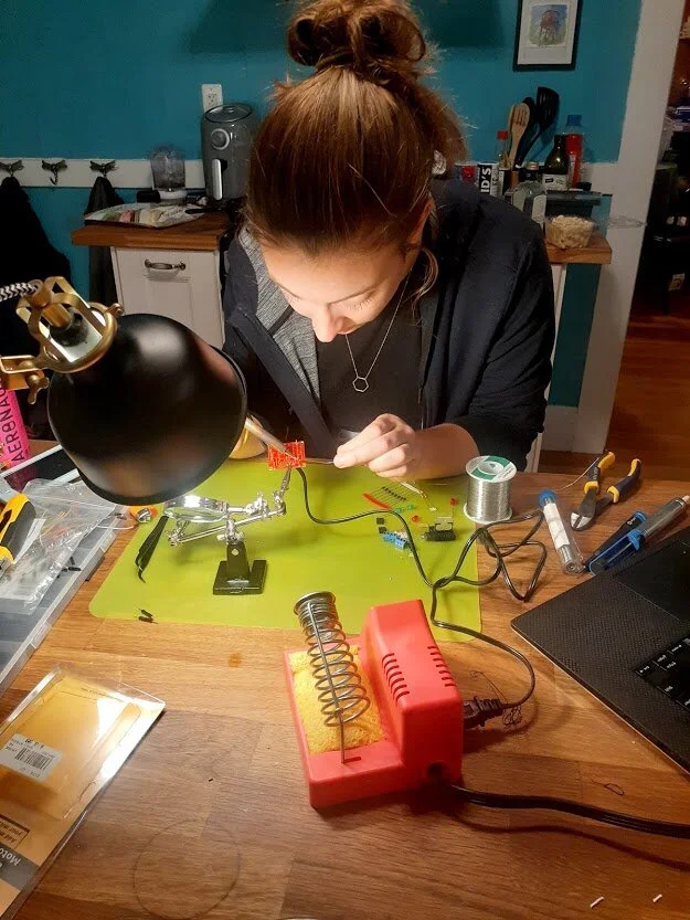
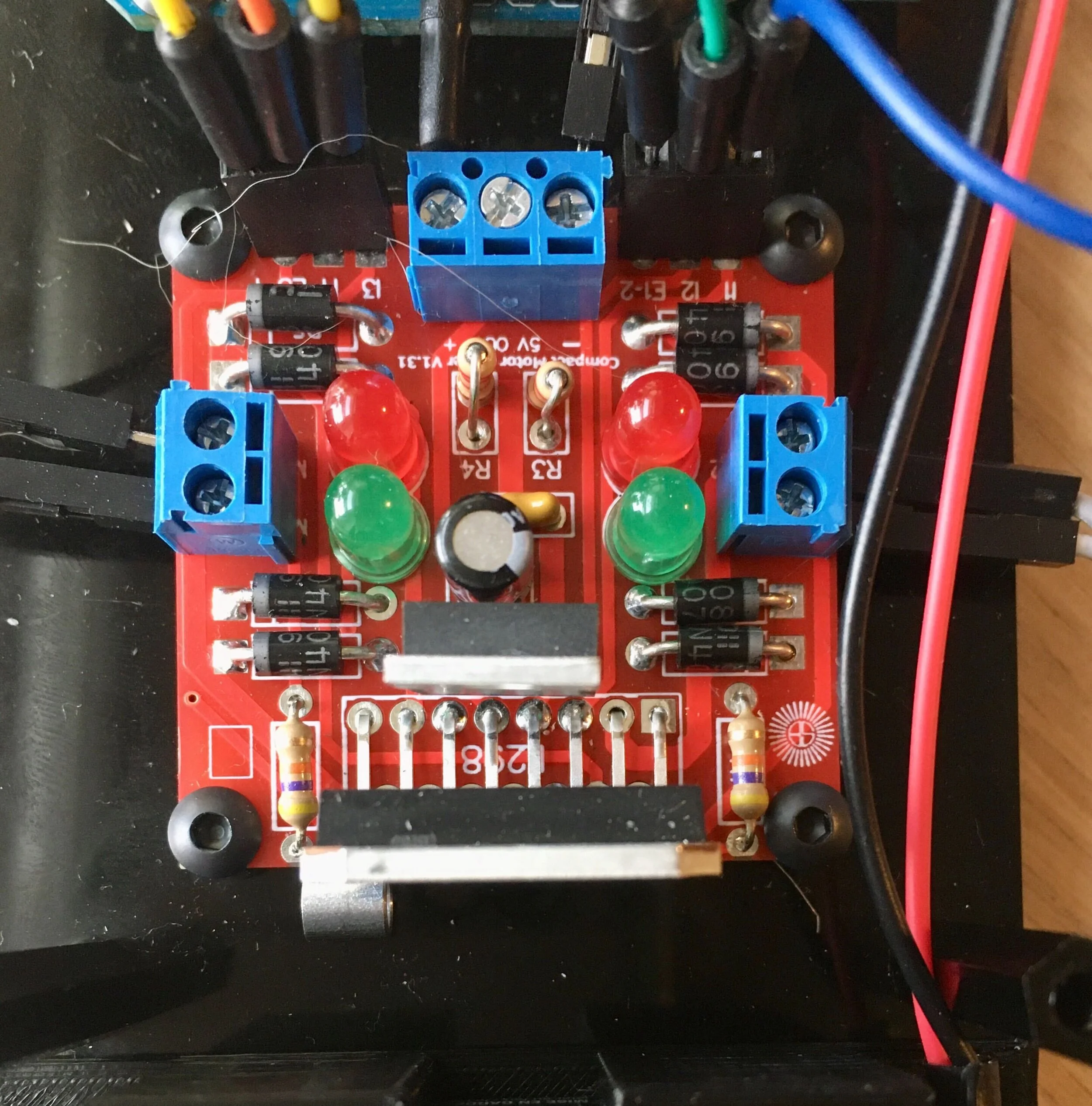
Soldering the motor driver PCB. This is a standard L298 and includes diodes which prevent back EMF from reaching the Arduino and other delicate components.
Close up of L298 motor driver after soldering on each component. Red and green LEDs represent forward and backward for each motor.
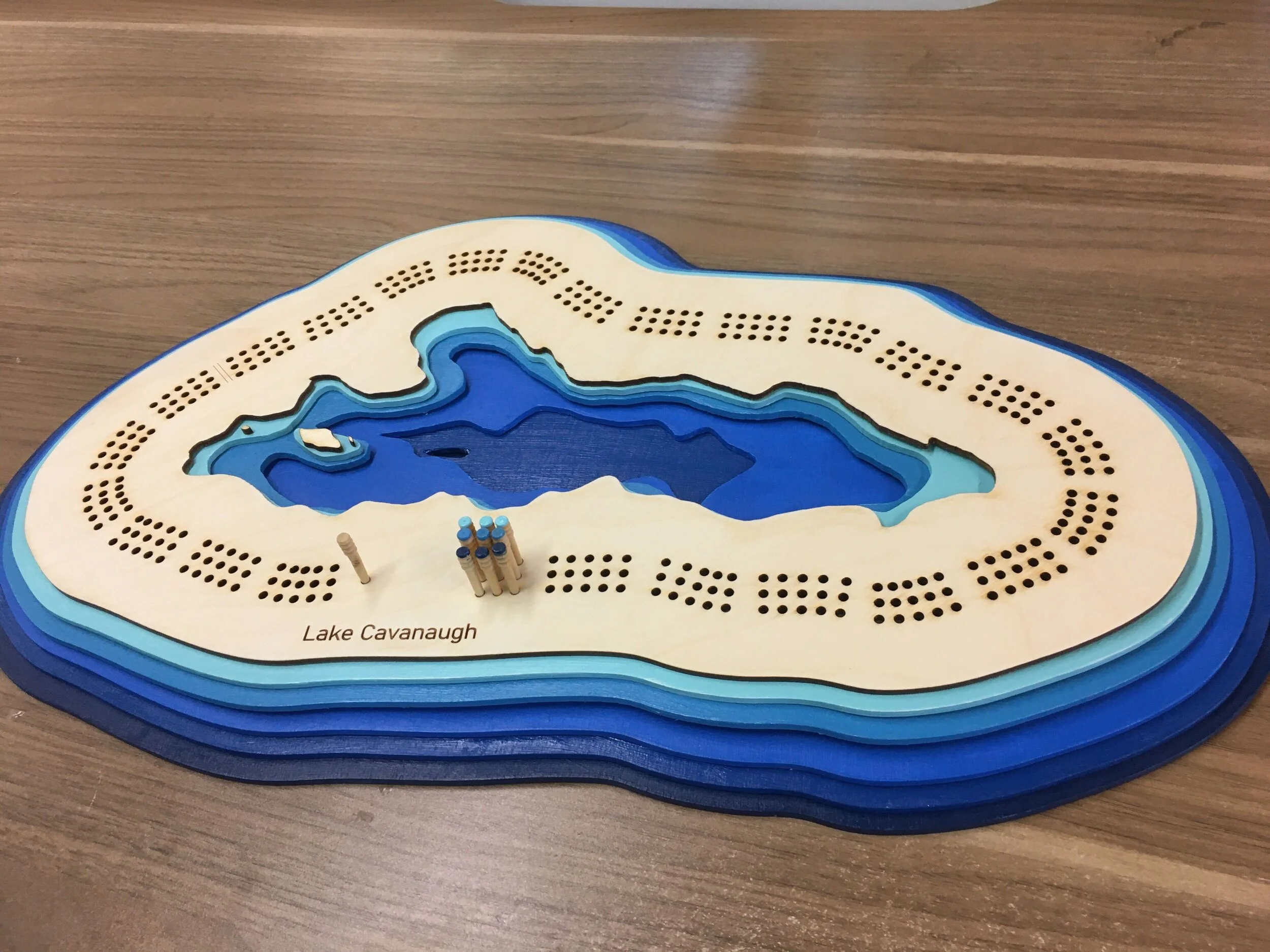
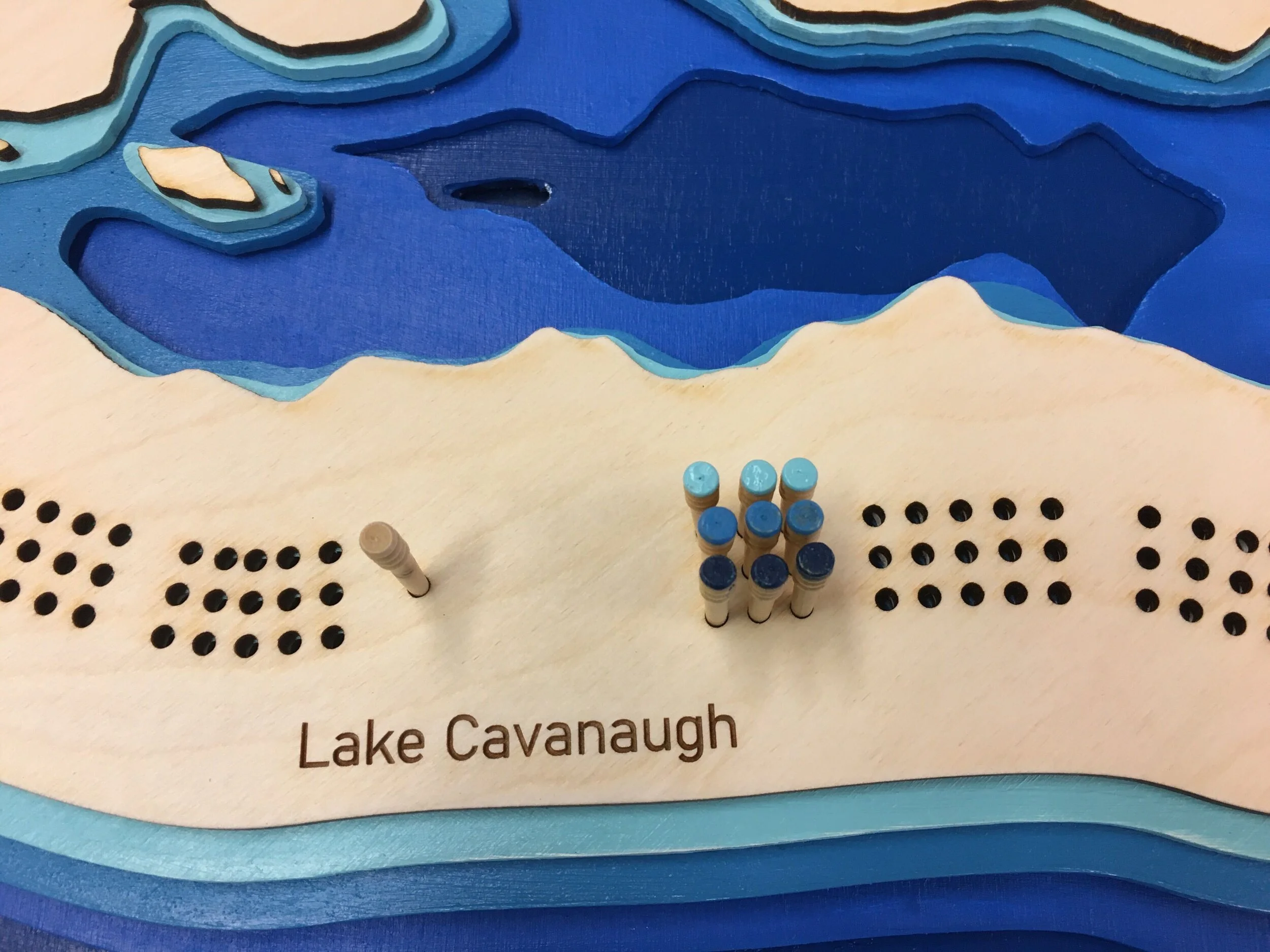
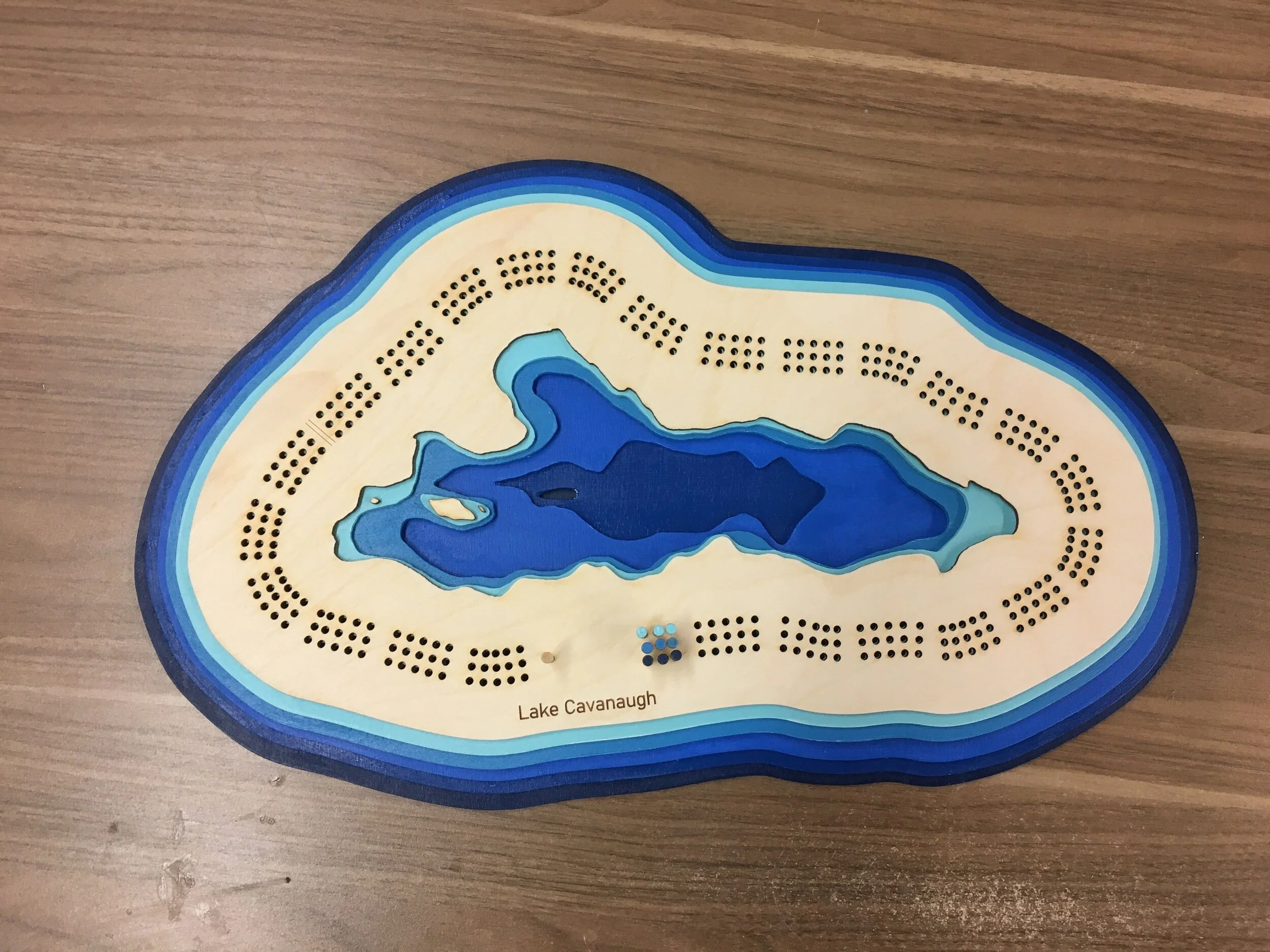
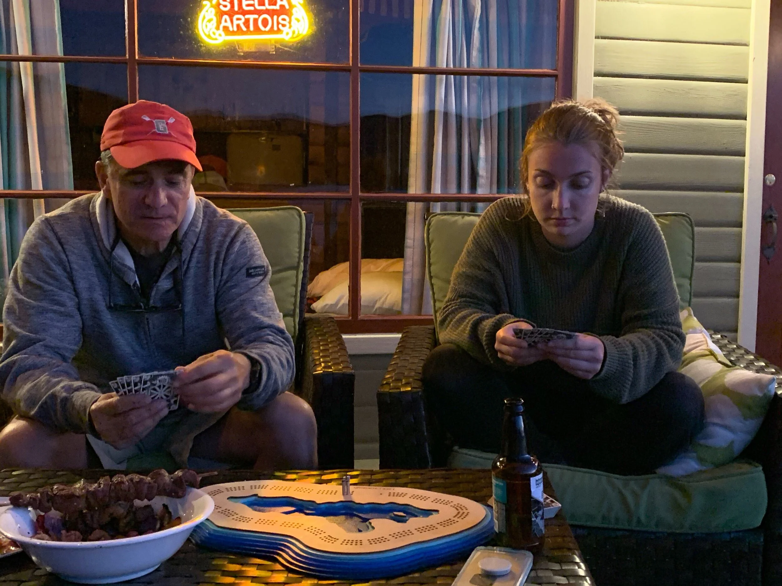
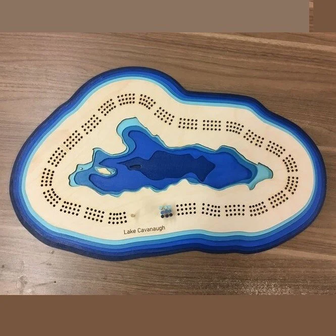
This project was a custom cribbage board I designed and built for my dad for Father’s day.
This project was featured in the Cribbage World monthly newsletter!
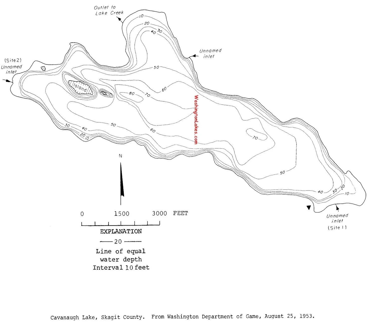
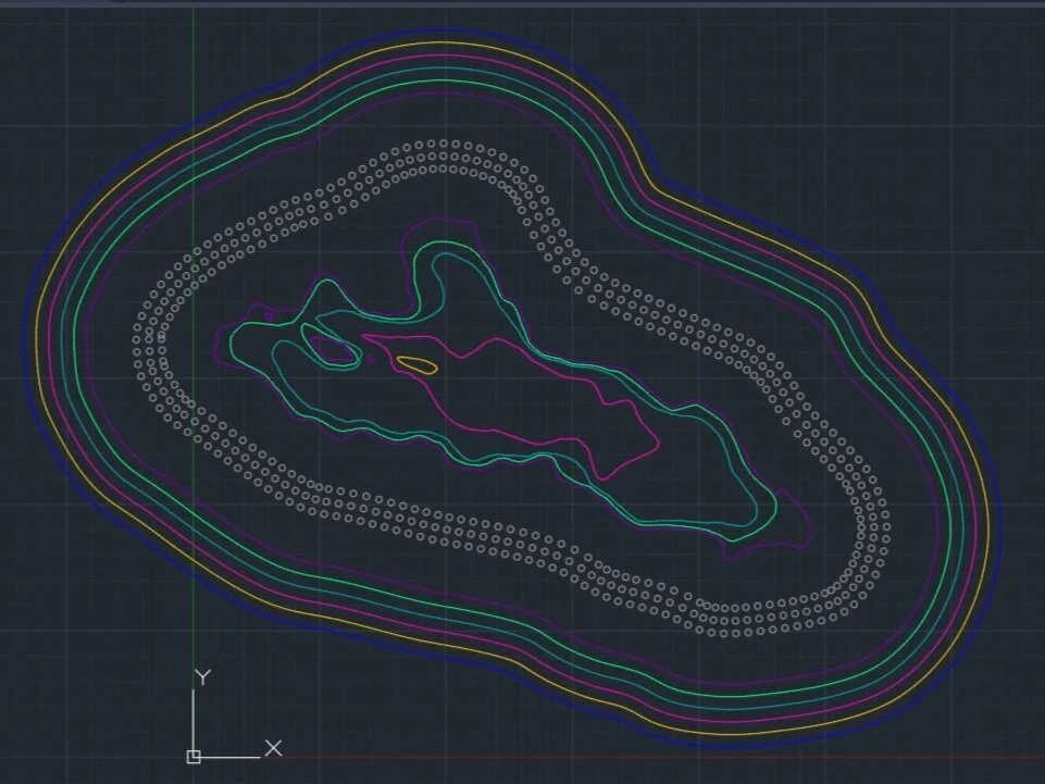
I started with a bathometric map of the lake, and decided to use 20 foot increments for the cribbage board rather than 10 foot so the finished project wouldn’t be too busy.
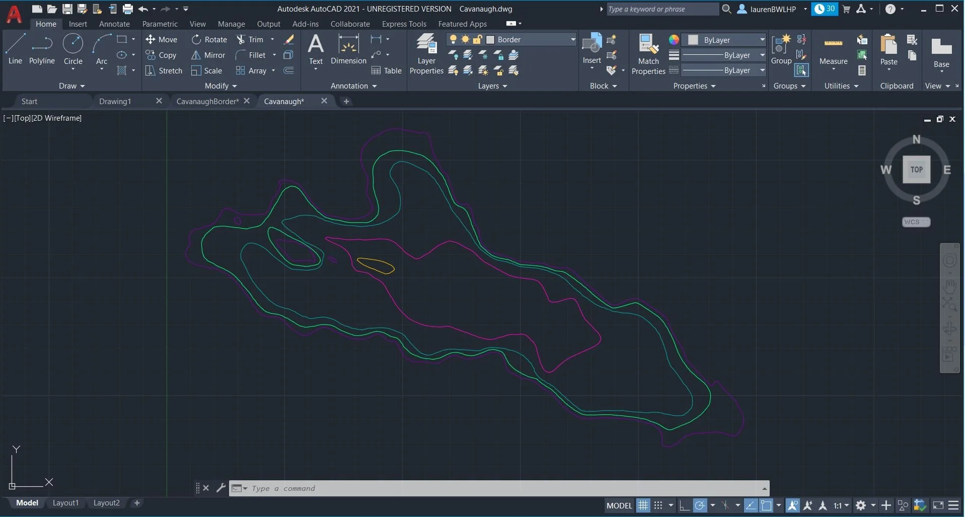
In order to create a 2D file, I traced each of the lines using the AutoCAD polyline tool. I then rounded each layer using the polyline>spline tool to give the lake a rounded, more organic shape. Doing this process manually for each layer maintained the desired level of detail.
After tracing and processing each layer, I created an offset border, and used this to create the hole pattern and the out border for each of the layers.
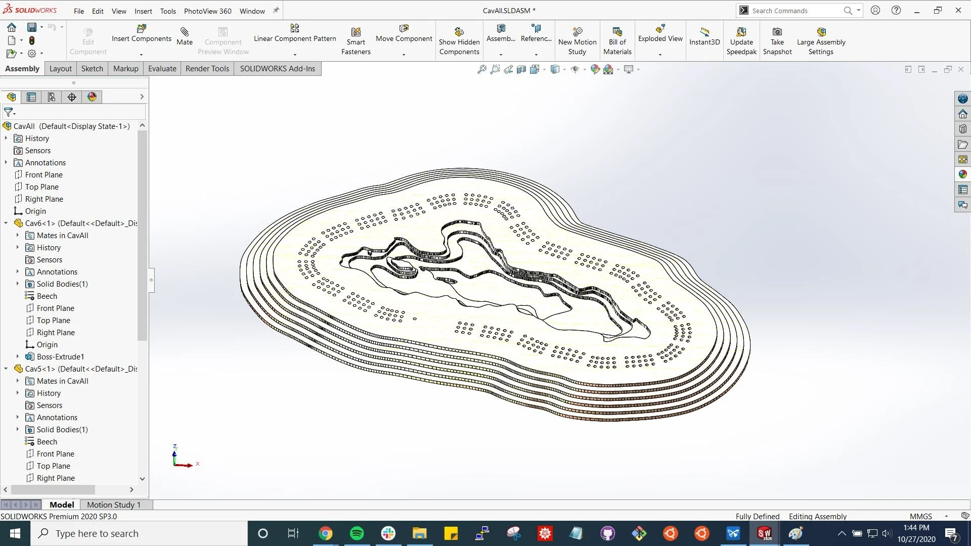
Solidworks model of each of the plywood layers stacked. I removed the extra holes in accordance with the standard cribbage board.
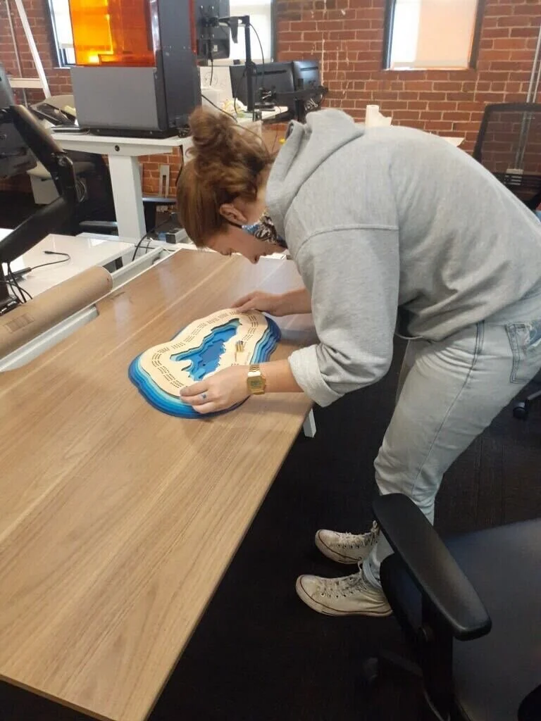
Each of the layers was laser cut from 1/8” plywood and painted with acrylic paint. On the first 3 layers, the cribbage holes double nicely as alignment holes.
Finished product.
Plain cribbage pegs painted with leftover paint from the layers.
I tend to stay busy with a wide variety of small scale projects, usually involving a laser cutter. I default to used AutoCAD and SolidWorks, but have enjoyed branching out to OnShape and OpenSCAD. This is a small sample of such projects, all done on my own time.
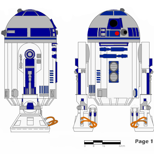
In order to get comfortable using AutoCAD I created a drawing of R2-D2 based on specifications I found online.
Expanded view of R2’s head module.
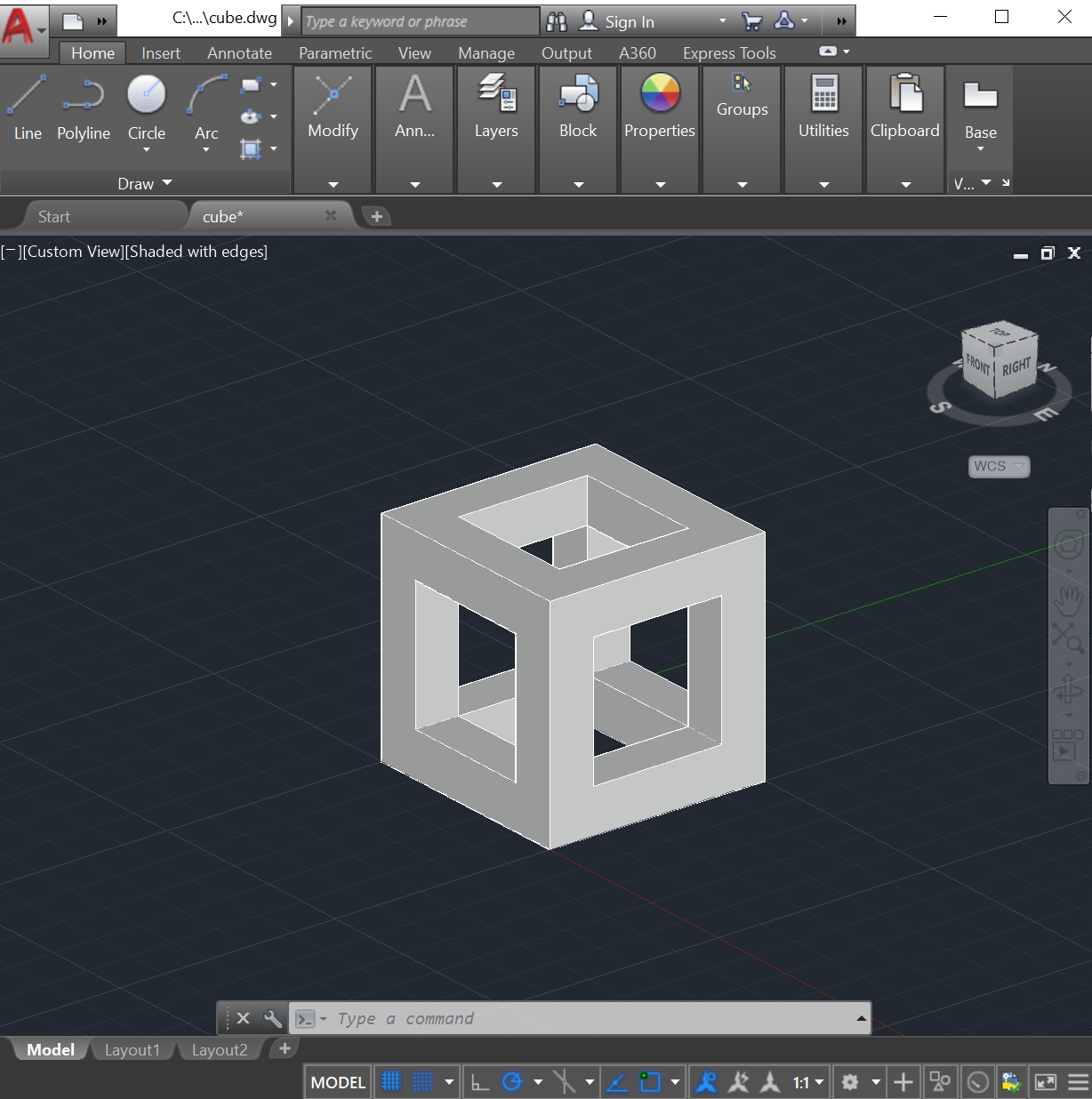
Experimenting with 3D modeling in AutoCAD.
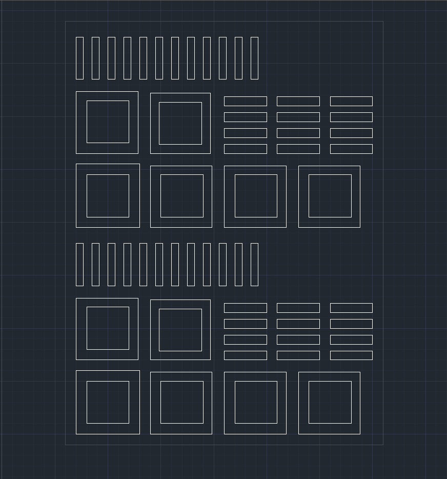
To create the model shown above, I used AutoCAD to create the 2D parts required to make a hollow cube. I then used a laser cutter to cut the required parts out of chipboard and assembled it using white glue.
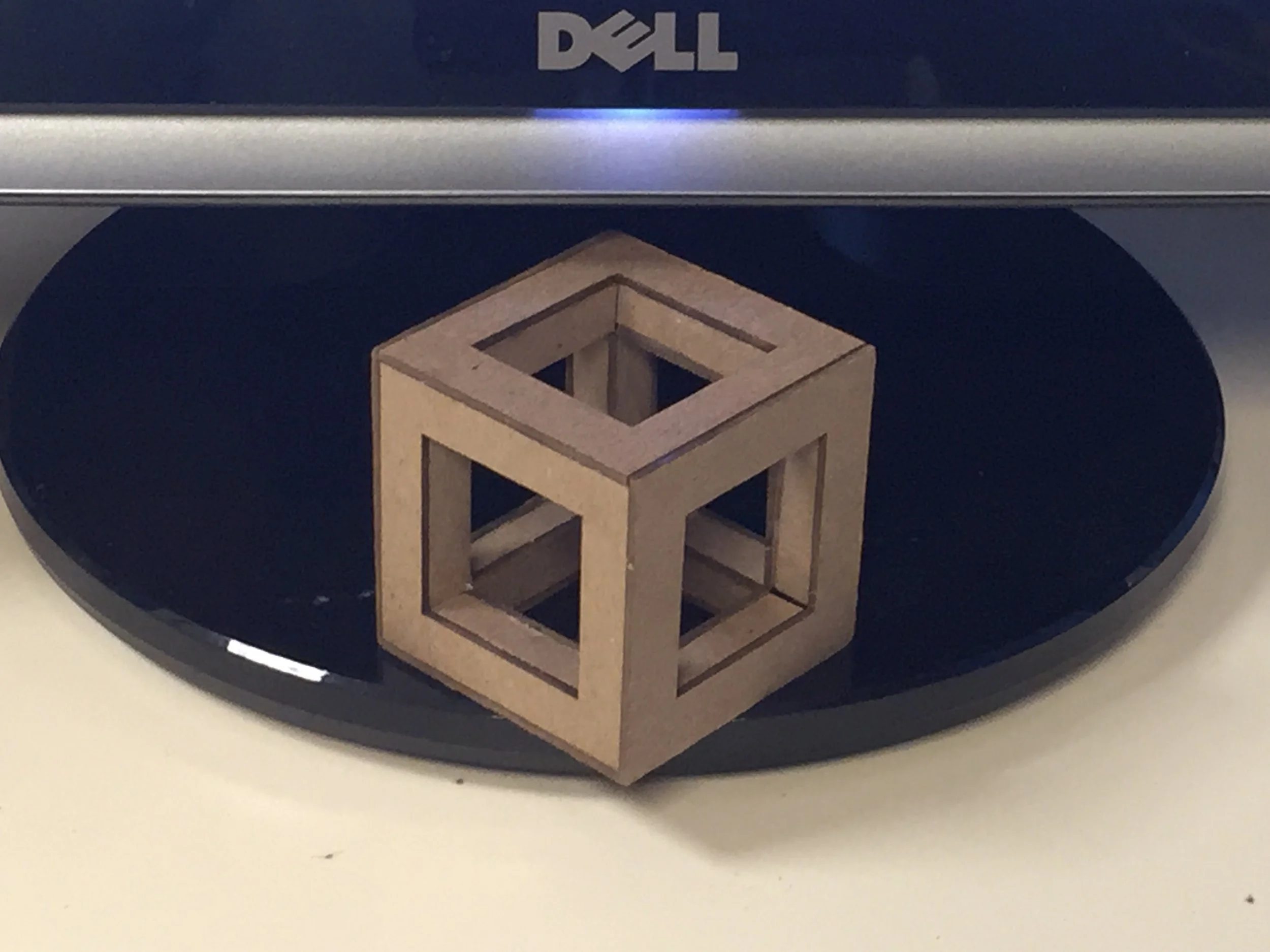
One of the finished cubes made from chip board on display by my dad’s monitor.
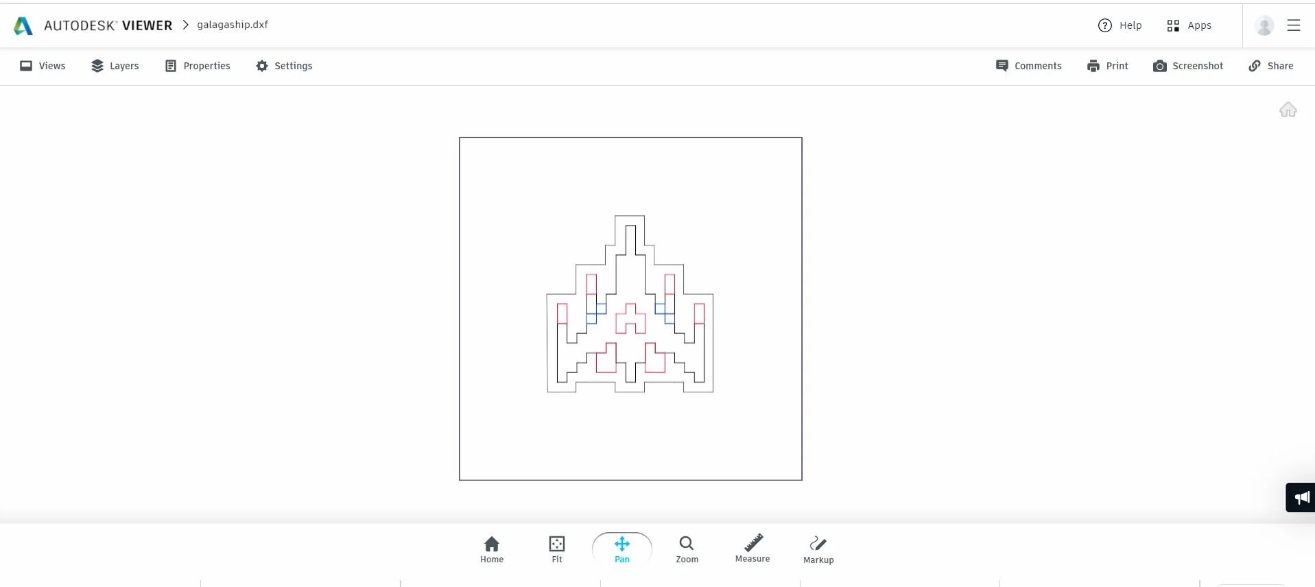
Galaga is my favorite classic arcade game. I decided to customize my new skateboard deck with racing stripes and the iconic spaceship. This image shows the AutoCAD DXF of all four layers needed to create the stencil.
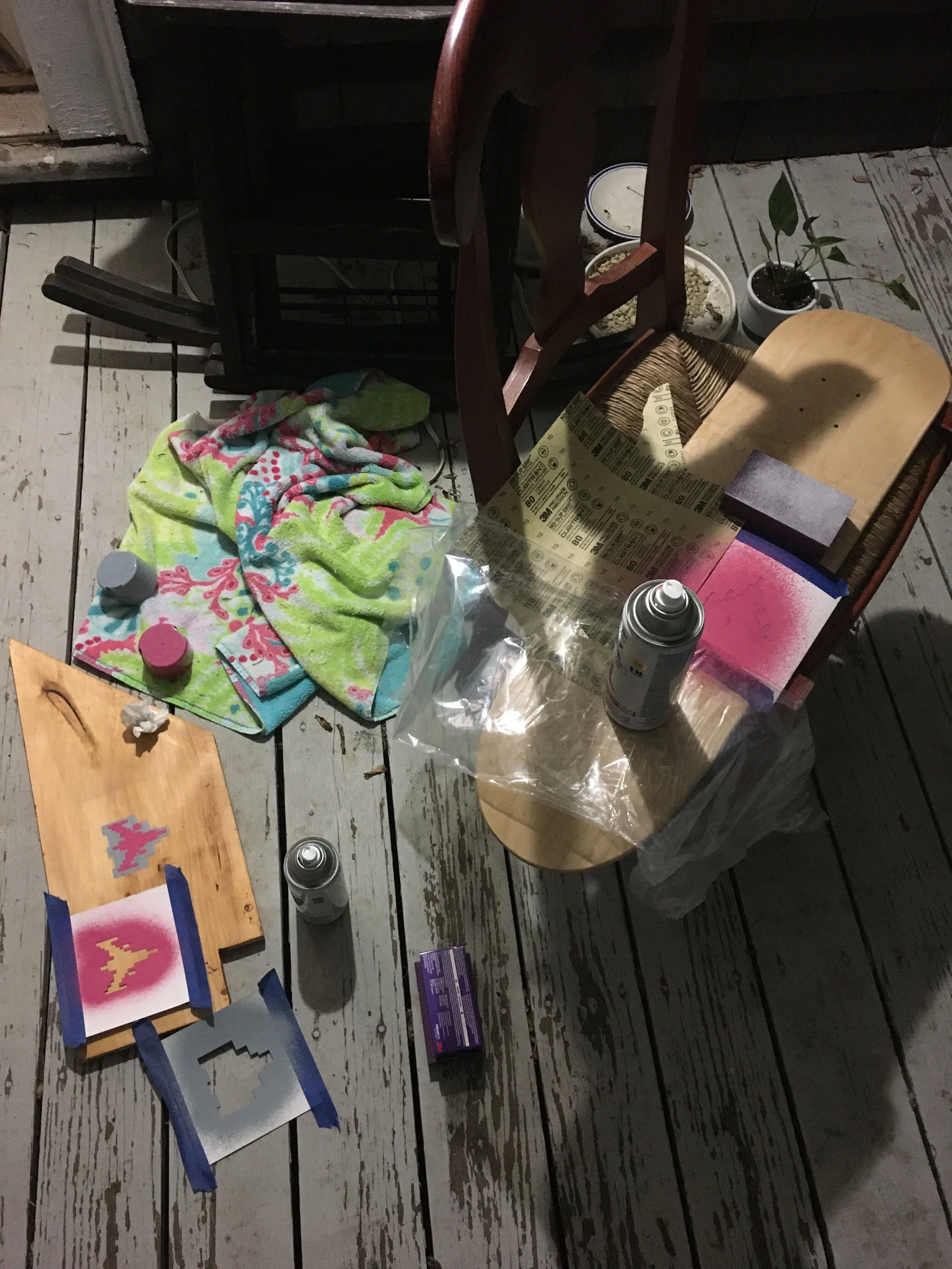
Spray paint setup, showing the stencils and a test piece of wood.
Final stencil on the bottom of my skateboard. I decided to go with unconventional colors to make it stand out.
Finished painted board.
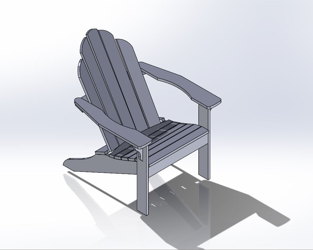
In an effort to increase my woodworking capabilities, I was interested in building my own Adirondack chair. This shows the 3D model based loosely on plans written by Norm Abram.
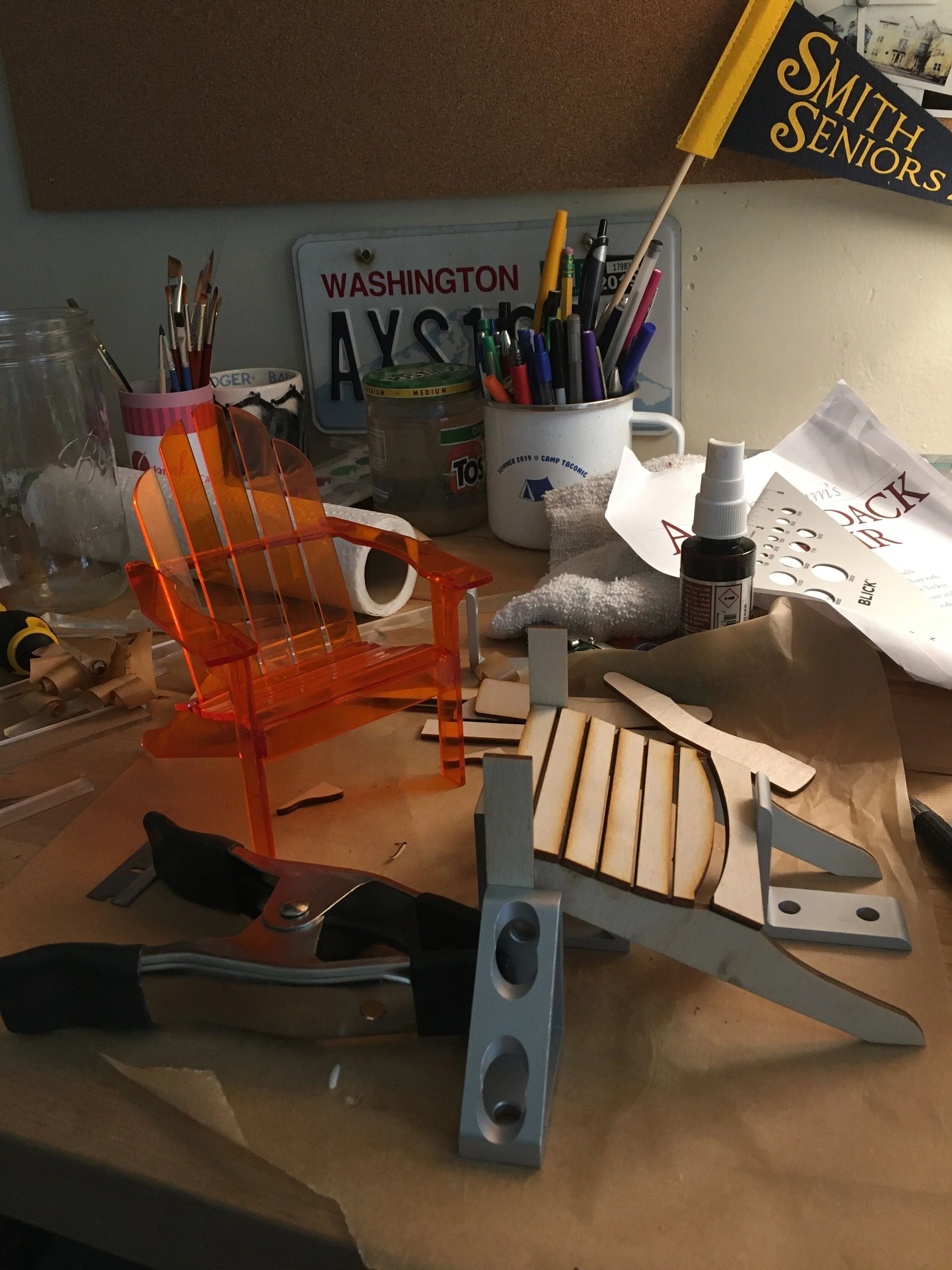
In order to evaluate the shape of my chair, I laser cut each component out of acrylic and ply wood and assembled it.
Model chairs shown in Acrylic, and partially assembled in thin plywood.
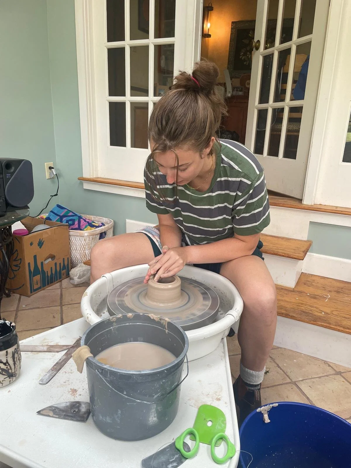
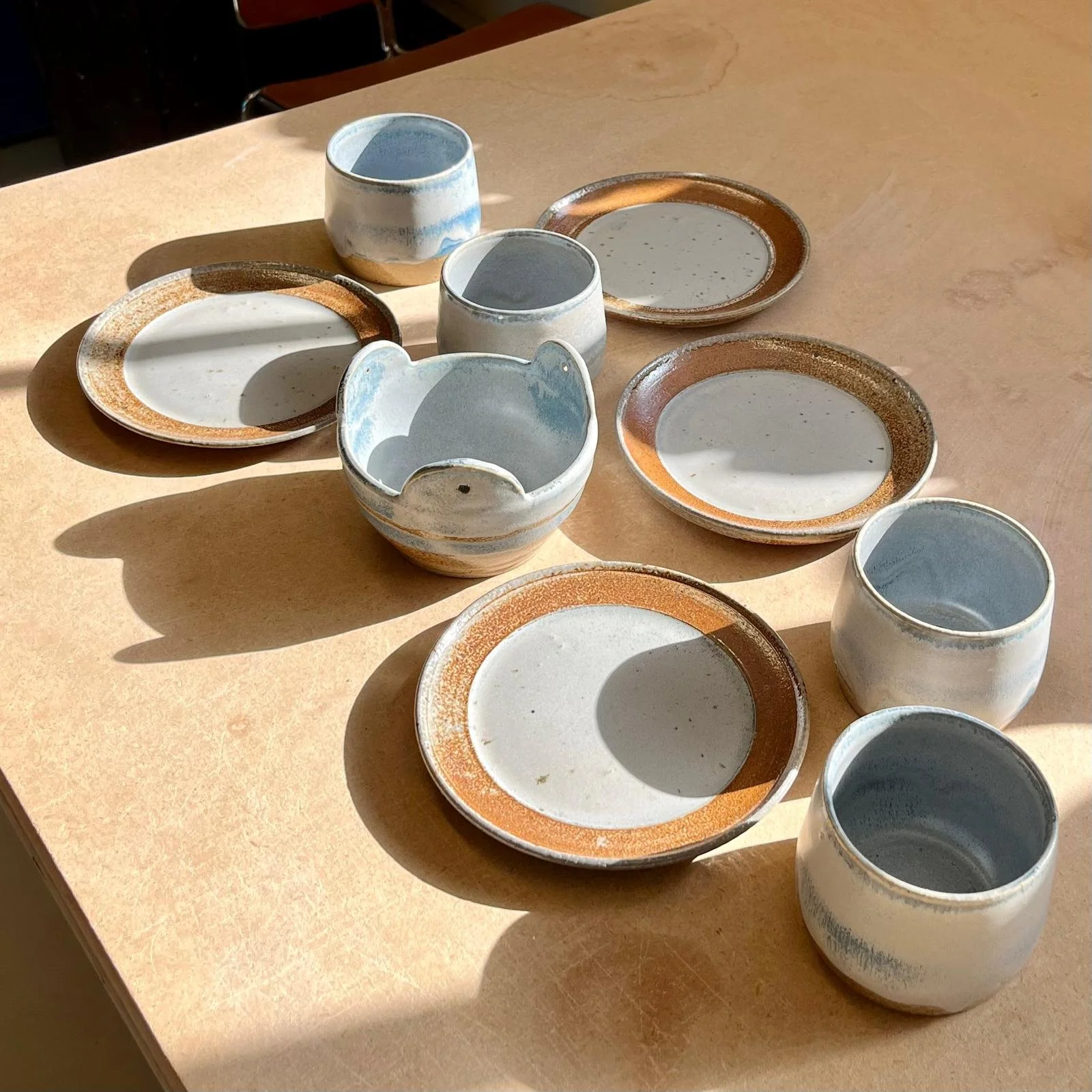
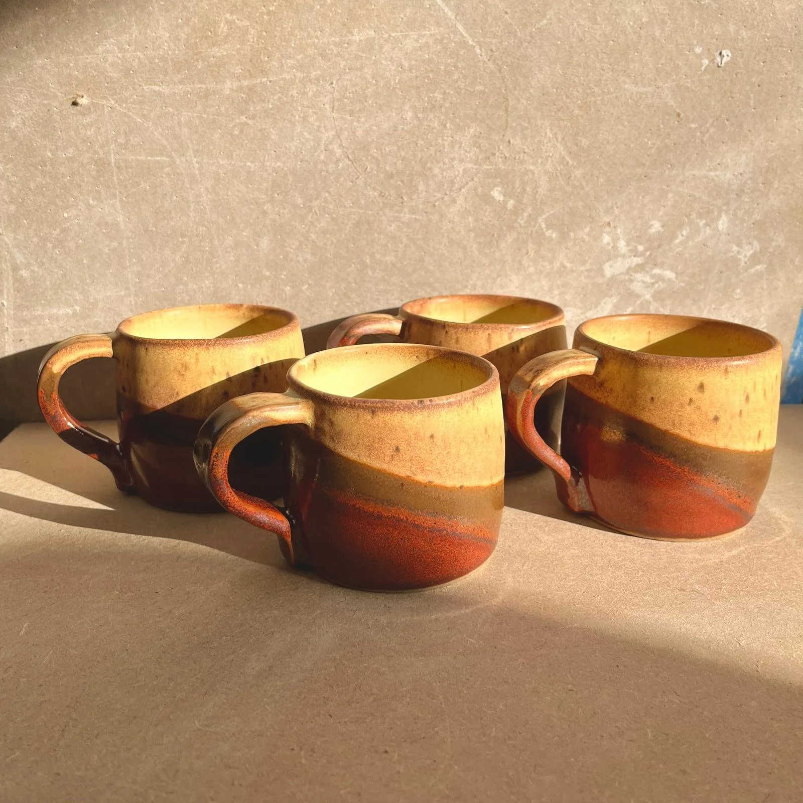
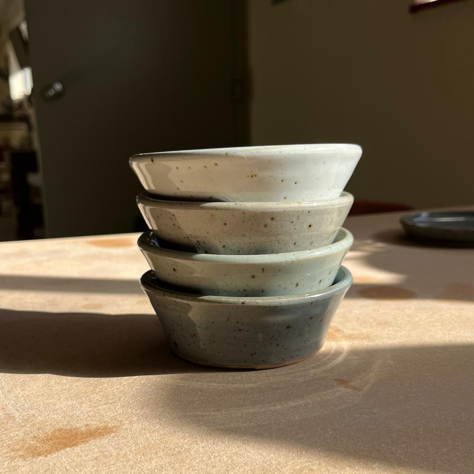
Something I love about ceramics is how much is challenges your mechanical intuition - changing the speed of the wheel, or the amount of moisture in the clay can change your results dramatically. It is a great art form for engineers!
The experts (not me!) say it is intuitive, but it helped me in the beginning to remember that it’s actually a closed-loop system between centrifugal force, viscosity, cohesion, and the always imprecise actions of one’s own limbs. It’s like becoming a squishy lathe - it’s very satisfying!
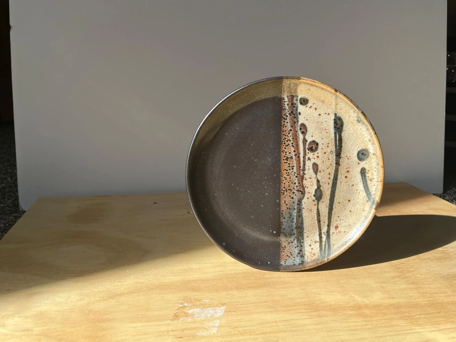
I practice at an amateur level, mostly creating pieces for friends and family - but have been featured in two gallery exhibits as well.
You can find more of my work here.
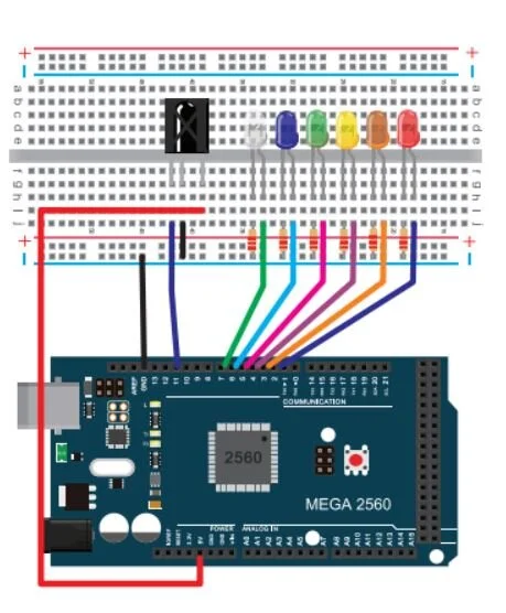
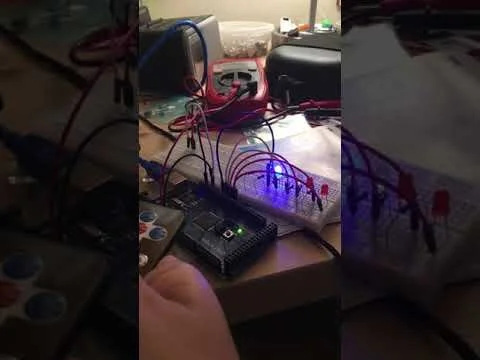
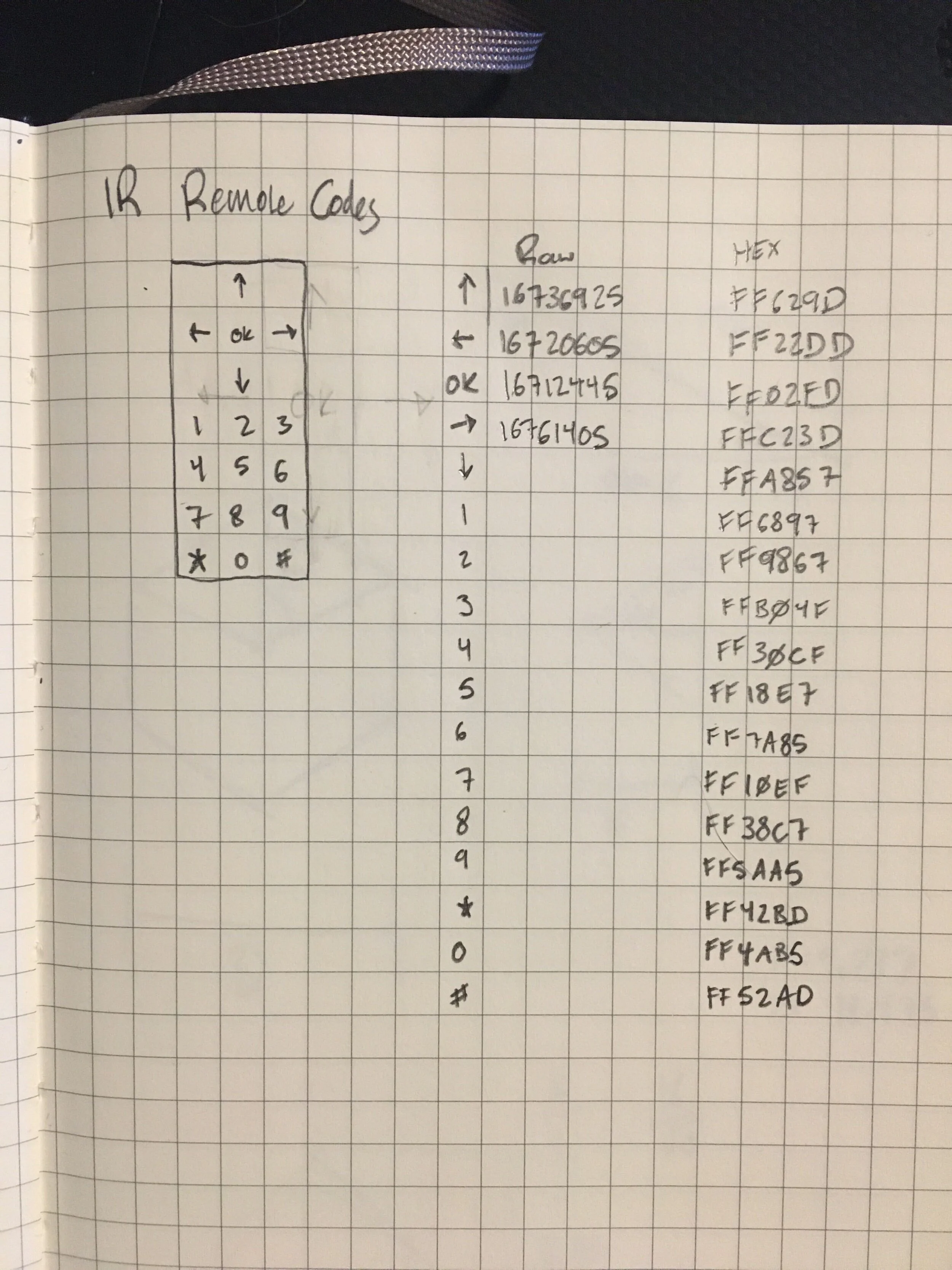
I used an Arduino Mega and an infrared remote to learn to turn on and off a series of LEDs. This quick project taught my the fundamentals of how IR remotes work, how those signals are processed and use that output to control a system.
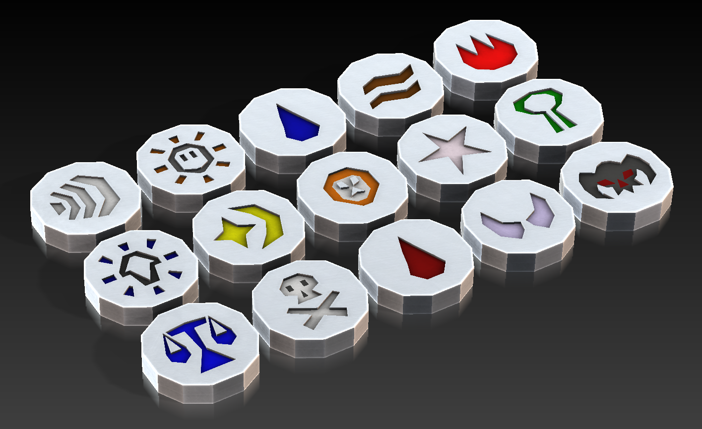
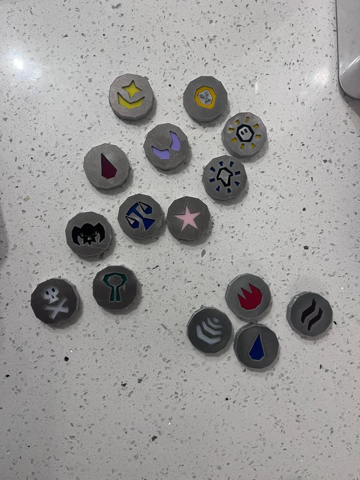
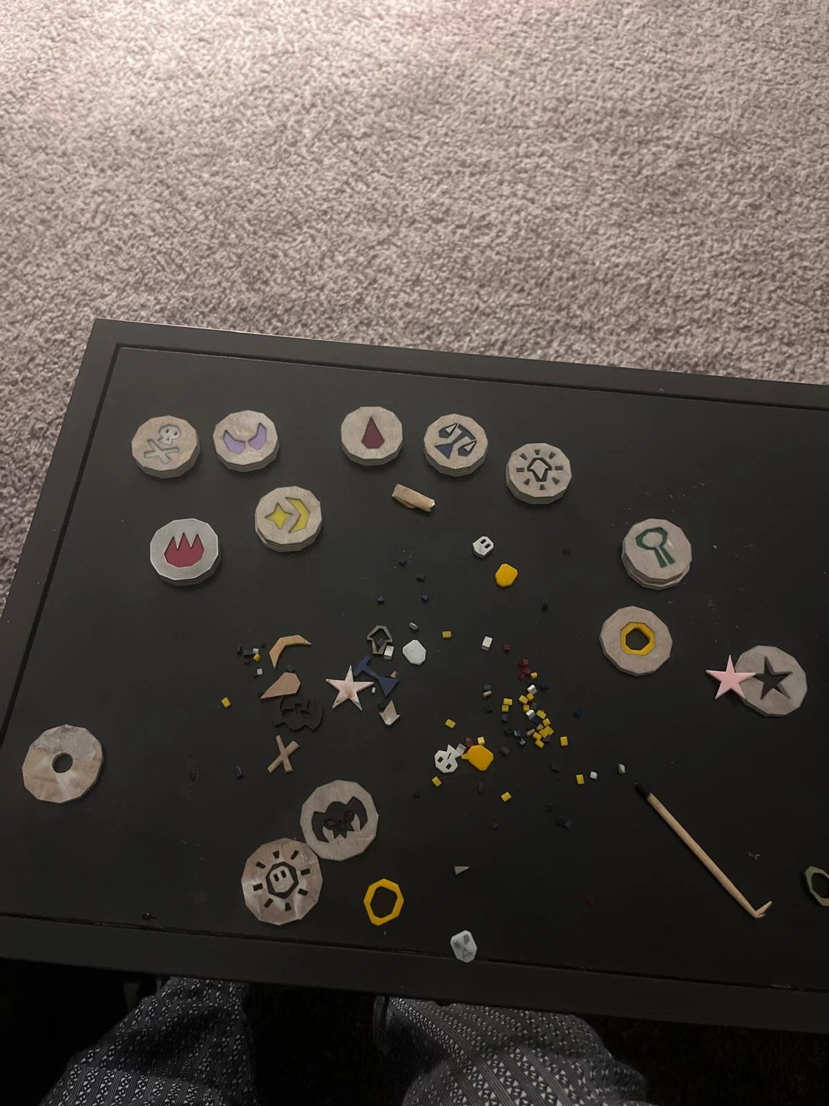
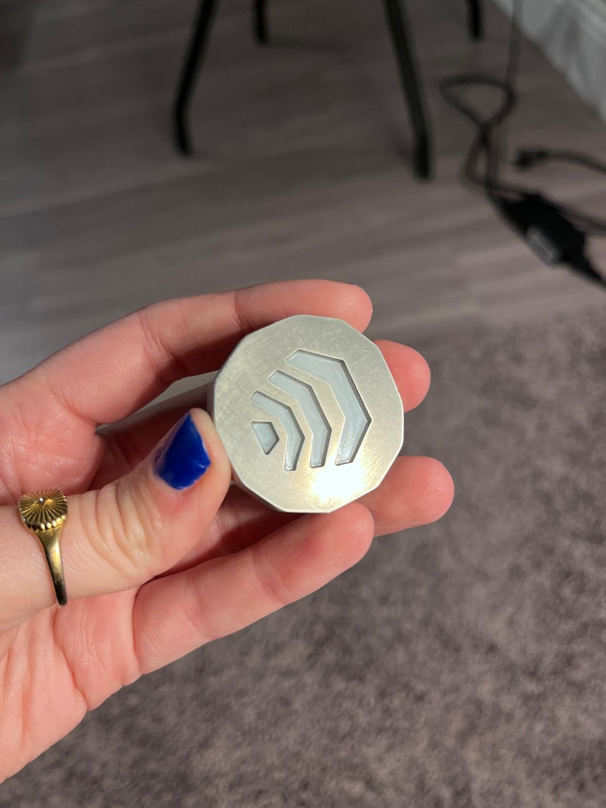
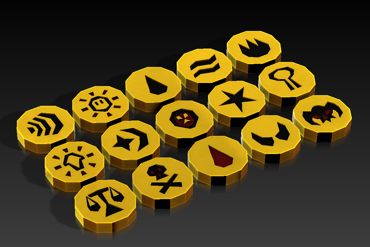
For this project, I wanted to recreate the runes from the online game Runescape, but retain the slightly magical metallic feeling I imagine the runes might have. In order to do this, I exported the 3D models from the game, created CAD and .dxf files for each piece, and used a waterjet to fabricate the bulk of the runes out of a sheet of aluminum. The inset pieces I cut from acrylic stock using a laser cutter. Finally, I assembled the runes and polished them to get a weathered look.