Over the course of the academic year, I have been working on a team of four to find a method by which we can 3D print an impeller for a centrifugal compressor.
The project trajectory followed a rigorous design process beginning with background research, and then concept generation, concept selection, and design verification with many smaller steps in between.
These machined impellers are similar to the one we are going to print and are roughly 15 inches in diameter. This design has several challenges to consider when printing it including its size, the required strength, the required heat resistance, and the overhanging features.
This cross-section of a compressor shows the impellers in place. Gas goes into the eye of each impeller, and is expelled at a higher velocity, increasing its pressure.
The printer we are using for our parts is the EOS M 290, which uses direct metal laser sintering. We are primarily using stainless steel, although we are pursuing one design concept in plastic. Printing in metal is the technique which will give the strongest final product, but comes with other complications such as thermal stresses and supports which are much more difficult to remove.
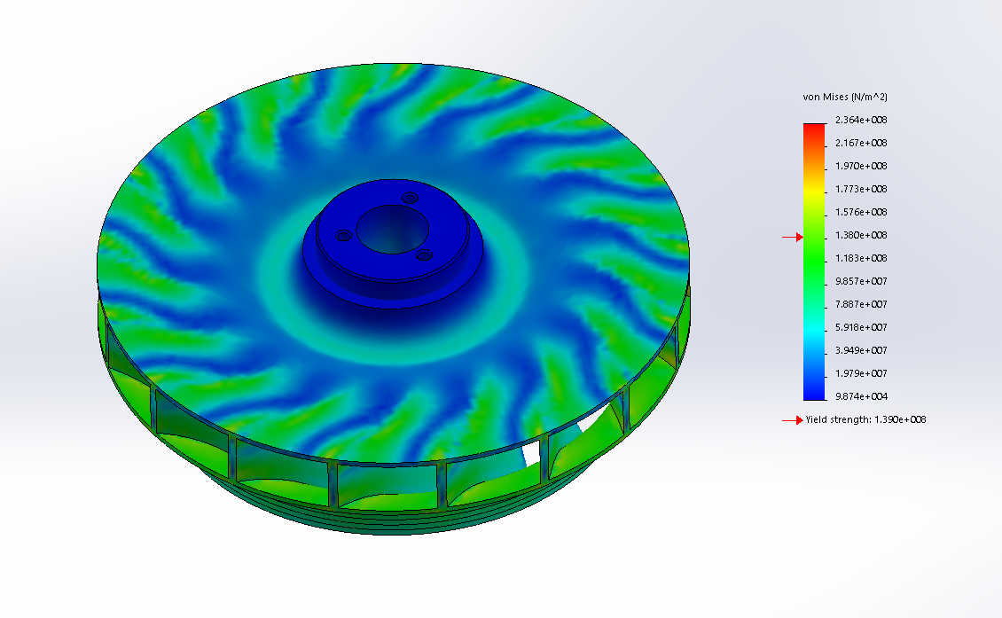
We have been using the Simulation feature in SolidWorks to run our Finite Element Analysis. This preliminary FEA shows the distribution of stresses on the impeller rotating at 15,000 rpm.
This is one of the ideas we are pursuing which will meet the challenges we encountered in printing the complex geometry of the impeller. We would print 17 of these slices and then weld them together to form the full impeller.
In this version of the printing process, we would print the top of the impeller and the blades, shown in green, and then either print or machine the rest of the part. The print is promising because it can be done without external supports and requires minimal welding.
In this version we would only print the blades, and then weld them to the rest of the part. The blades can be printed in almost any metal 3D printer, but this design requires a lot of complex welding.
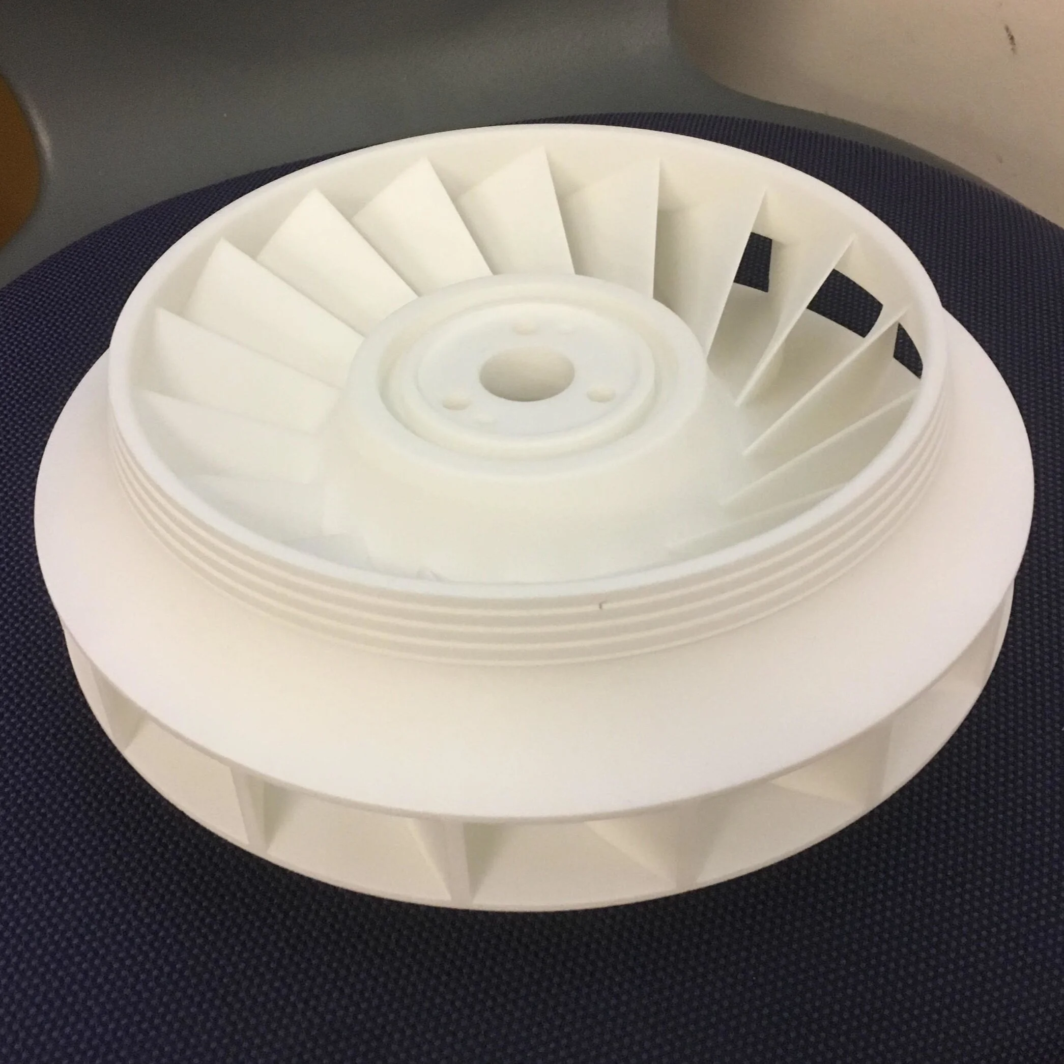
In this version, the entire impeller is printed in plastic with removable supports. The simplicity of this process is its main advantage, however the material will not hold up at full speed conditions making this concept our back up plan.
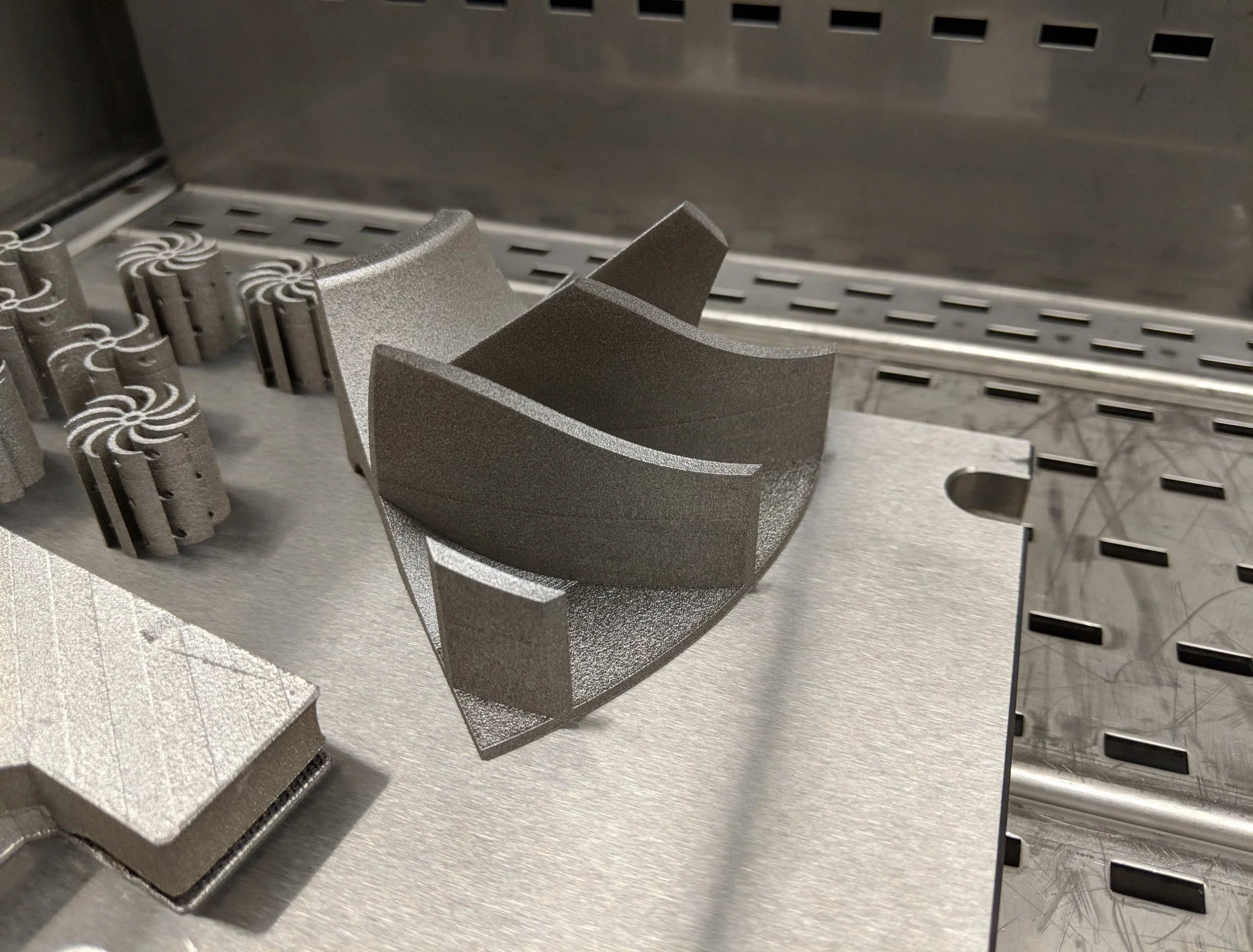
This test print is our first completed prototype, printed in stainless steel on the EOS M 290. This prototype is the partial print idea and required no supports to print. We will proceed by attempting to weld and strength test this piece.
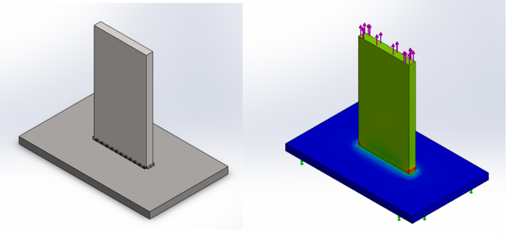
We researched different welding options and modeled them in SolidWorks, as well as creating complete FEAs and modeling the supports we were going to need. By the end on March, we finalized our design and will began to write our final report and recommendation.
This image shows our printed test parts after failing in a tensile strength test on an INSTRON machine. On top is our welded part, which failed parallel to the welds, and the bottom was one solid 3D printed part, which failed where the geometry was narrowest. Unfortunately, the welds on the 3D printed steel did not reach the yield strength we hoped, and it is much harder to weld than traditionally manufactured steel.
Our final design for metal 3D printing is shown above. It will be printed in three parts, as shown. The bottom part with the slots will be welded to the middle part with the tabs. The spacer (on top) will be aligned on the axle that these parts rotate on without welding.
Using Materialize Magics, we were able to generate several possible support configurations for the cover component.
Whole impeller printed in plastic at around 61% scale. This is our second recommendation, dependent on complications with welding.
Over the course of one summer I conducted research with a professor in the Smith College Physics Department. This research concerned the conditions of a 'scalar field' in the early universe and the type of expansion we would expect to see.
The goal of this type of research is to learn a little bit more about the nature of the universe at its beginning. Throughout the summer I learned more about cosmology and high energy physics, how to program in Mathematica and how to analyze complex differential equations.
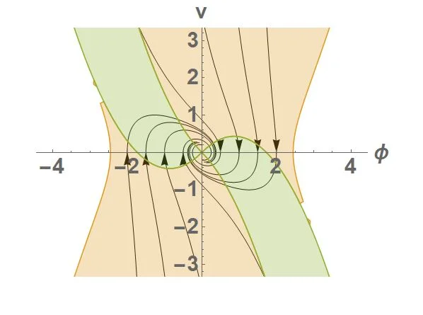
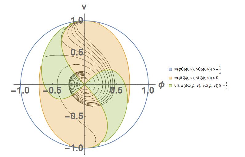
This phase diagram shows the motion of the field and its derivative as Φ and v respectively.
This Poincare Plot shows the same function as above with the addition of the blue circle. This circle represents the point where the function becomes infinite, and shows the limits where this behavior is happening.
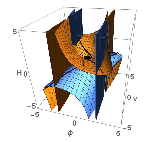
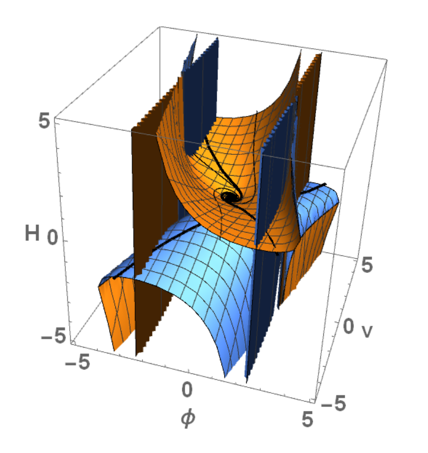
This image shows the same function, but with the Hubble Constant (rate of expansion of the universe) on the third axis. The orange and blue surfaces show the regions where we would expect the plots to match up with the current theory.
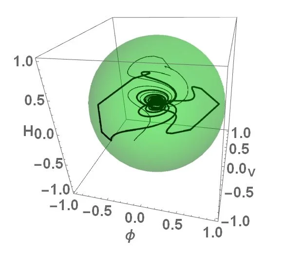
This image shows the same 3D phase plot once again, but the green surface shows where the function goes to infinity.
This project was completed with a group of other students. We reverse engineered a Stirling Engine by dismantling it and each used SolidWorks to model the components we needed to machine. We then constructed our own Stirling engines based off of our CAD drawings in Smith's Center for Design and Fabrication (CDF).
This process was completed over the course of 5 days during the break before spring semester.
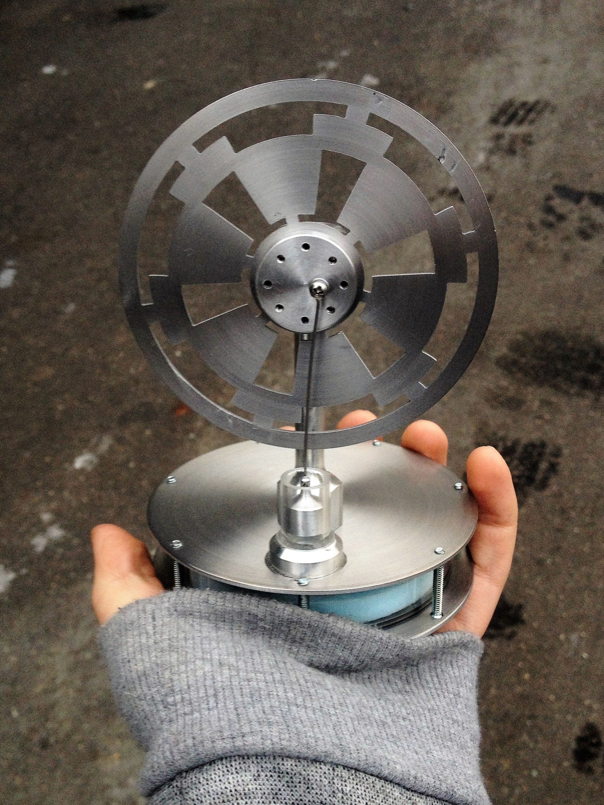
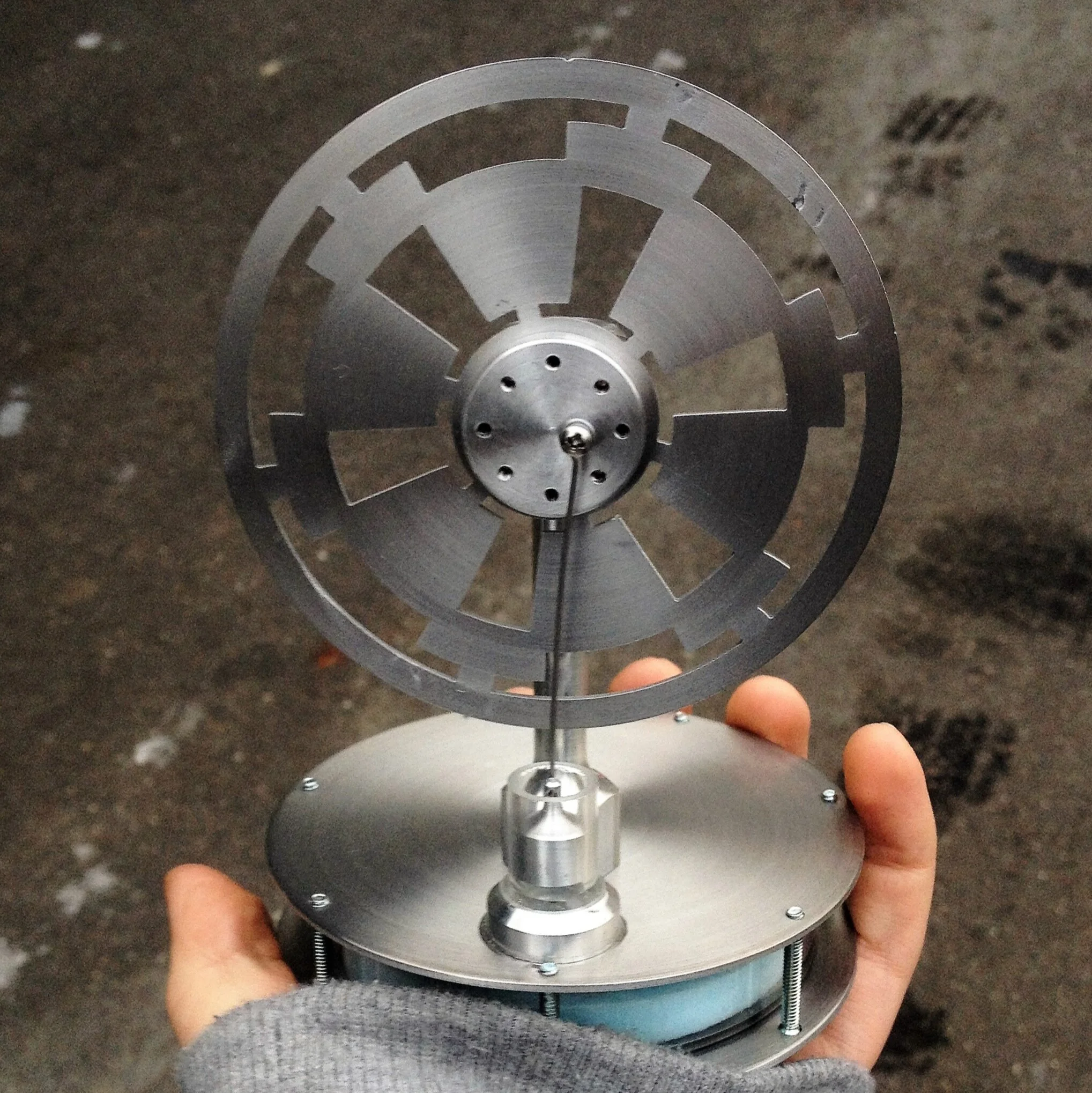
My Stirling Engine, fresh out of the CDF. When placed on a cup of hot water, the temperature differential between the bottom and top plates causes expansion and compression of the air inside the cylinder, which in turn makes the flywheel spin.
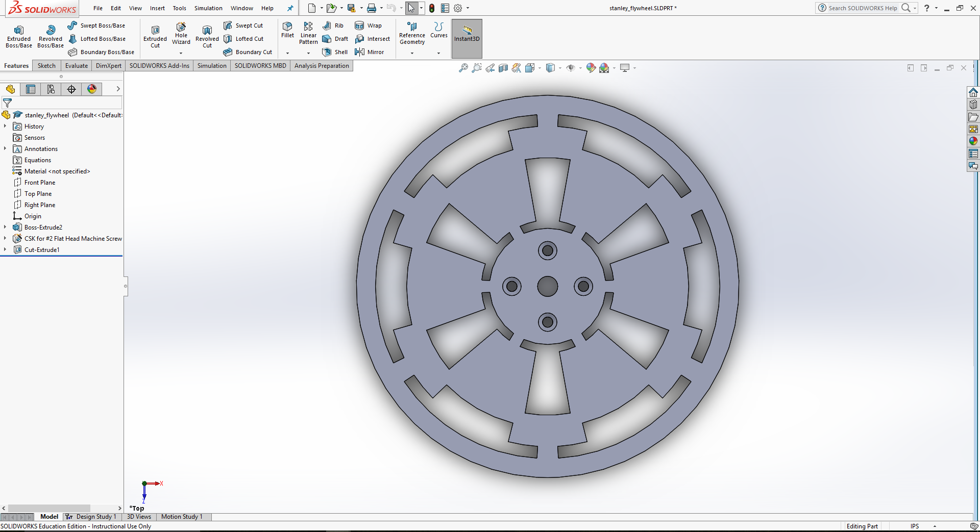
Custom flywheel, designed to look like the imperial symbol from Star Wars.
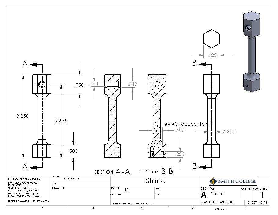
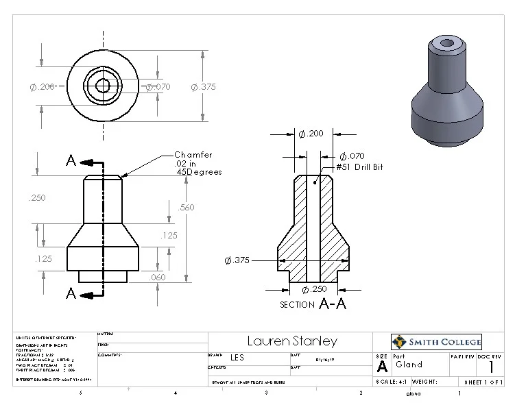
After modeling the necessary parts in SolidWorks, I created drawings to be used in the fabrication center.
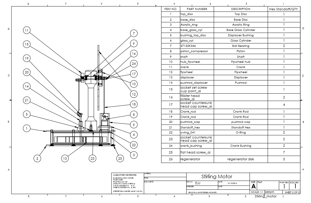
This file includes all the parts required for the Stirling engine, including those we could not machine.
Runs on the temperature differential between a cup of tea and ambient.